


SYSTEM / Control System
T2-1-60
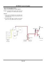
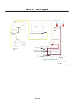
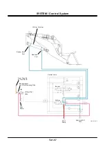
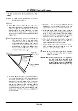
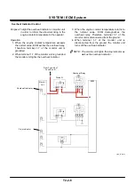
Lift Arm Auto-Leveler Upward Control (Optional)
Purpose: To locate the lift arm between the horizon
and the highest position
Operation:
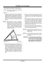
1. If the SET position of the lift arm auto-leveler
upward set switch is selected after the lift arm is
located within the allowable location of the lift arm
auto-leveler (a’ in the illustration), the signal from
the lift arm angle sensor is memorized by MC,
and that is the lift arm auto-leveler upward stop
location.
NOTE: When the lift arm is outside a’, although the
SET position of the lift arm auto-leveler
upward set switch is selected, the lift arm
auto-leveler upward stop position cannot
be set. In case setting was thus unsuc-
cessful, or setting in a different position is
needed, again set the lift arm auto-leveler
upward stop position.
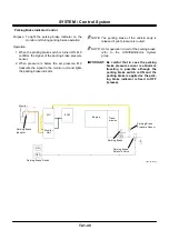
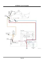
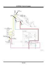
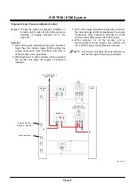
2. When the lift arm auto-leveler upward switch is
turned ON, terminal A-25 of MC is grounded, and
excites the electromagnet on the lift arm raise
side of the pilot valve. When the lift arm control
lever is moved to the lift arm raise detent position
(position to pull farther than the raise position),
the lift arm control lever is retained by the elec-
tromagnet on the lift arm raise side, and pressure
oil from the pilot valve is supplied to the control
valve.
3. Pressure oil from the main pump flows to the
bottom side port of the lift cylinder through the lift
arm spool in the control valve, and raises the lift
arm.
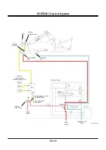
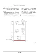
4. When the lift arm angle sensor moves to the lift
arm auto-leveler upward stop position, terminal
A-25 of MC is hot grounded, and the electro-
magnet on the lift arm raise side is unexcited.
Thus the lift arm control lever returns to the neu-
tral position, and pressure oil from the pilot valve
stops flowing to the control valve.
5. As the lift arm spool in the control valve also re-
turns to neutral, the lift arm stops at the lift arm
auto-leveler upward stop position.
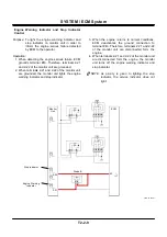
NOTE: Above the lift arm upward set position, the
electromagnet on the lift arm raise side is
always excited.
NOTE: In case the lift arm angle sensor is abnor-
mal, the lift arm auto-leveler upward control
is not made.
IMPORTANT: In case either the lift arm angle sen-
sor or MC has been replaced, make
learning control of the lift arm angle
sensor. (Refer to the OPERATIONAL
PERFORMANCE TEST/Adjustment.)
a (Lift Arm Upward
Work Range)
Position of
Lift Arm Tip Pin
Position of
Lift Arm Foot Pin
a’ (Lift Arm
Auto-Leveler
Upward
Allowable Setting
Range)
Summary of Contents for ZW180
Page 1: ......
Page 2: ......
Page 8: ...4GDT 1 2 Blank ...
Page 10: ...GENERAL Specification T1 1 2 Blank ...
Page 38: ...GENERAL Component Specifications T1 3 14 Blank ...
Page 39: ...MEMO ...
Page 40: ...MEMO ...
Page 42: ...4GDT 2 2 Blank ...
Page 56: ...SYSTEM Control System T2 1 14 Blank ...
Page 82: ...SYSTEM Control System T2 1 40 Blank ...
Page 92: ...SYSTEM Control System T2 1 50 Blank ...
Page 106: ...SYSTEM Control System T2 1 64 Blank ...
Page 116: ...SYSTEM ECM System T2 2 10 Blank ...
Page 128: ...SYSTEM Hydraulic System T2 3 12 Blank ...
Page 147: ...SYSTEM Hydraulic System T2 3 31 Blank ...
Page 150: ...SYSTEM Hydraulic System T2 3 34 Blank ...
Page 184: ...SYSTEM Electric System T2 4 34 Blank ...
Page 185: ...MEMO ...
Page 186: ...MEMO ...
Page 195: ...COMPONENT OPERATION Pump Device T3 1 7 Blank ...
Page 212: ...COMPONENT OPERATION Control Valve T3 2 4 T4GB 03 02 003 1 2 3 4 5 7 8 9 10 11 7 6 ...
Page 214: ...COMPONENT OPERATION Control Valve T3 2 6 T4GB 03 02 003 1 2 3 4 5 7 8 9 10 11 7 6 ...
Page 226: ...COMPONENT OPERATION Control Valve T3 2 18 Blank ...
Page 232: ...COMPONENT OPERATION Control Valve T3 2 24 Blank ...
Page 248: ...COMPONENT OPERATION Steering Pilot Valve T3 4 6 Blank ...
Page 258: ...COMPONENT OPERATION Steering Valve T3 5 10 Blank ...
Page 274: ...COMPONENT OPERATION Pilot Valve T3 6 16 Blank ...
Page 282: ...COMPONENT OPERATION Pilot Valve T3 6 24 Blank ...
Page 299: ...COMPONENT OPERATION Ride Control Valve T3 8 5 Blank ...
Page 306: ...COMPONENT OPERATION Ride Control Valve T3 8 12 Blank ...
Page 348: ...COMPONENT OPERATION Drive Unit T3 9 42 Blank ...
Page 371: ...MEMO ...
Page 372: ...MEMO ...
Page 374: ......


