


SYSTEM / Electrical System
T2-4-30
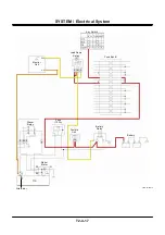
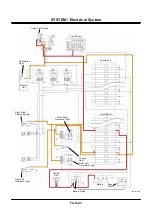
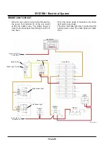
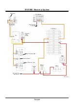
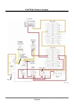
PARKING BRAKE CIRCUIT
•
When the key switch is turned to the ON position,
the power from terminal M excites the battery
relay through fuse #8 of fuse box A.
•
The battery power flows to parking brake relay 1
through fuse #2 of fuse box B.
•
The power flows to terminal D of parking brake
relay 1 through terminal B of parking brake relay 1.
The power flows to terminal B of parking brake
relay 2 and terminal B of the parking brake switch.
•
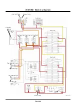
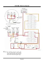
The parking brake switch consists of three circuits
of ON, NEUTRAL and OFF, and it is kept ON
when turned ON, and it is automatically returned
to NEUTRAL when turned OFF.
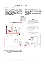
•
When the parking brake switch is turned to the
OFF position, current flows from terminal E of the
parking brake switch to terminal A of parking
brake relay 2 and the parking brake solenoid
valve.
•
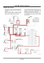
At this time, if the engine is not running, parking
brake relay 1 is excited as terminal 2-18 of the
monitor unit is grounded.
•
Therefore, the parking brake cannot be released
as the power between parking brake relay 1 and
terminal B of the parking brake switch and
terminal B of the parking brake relay is blocked.
•
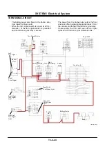
If the engine is running, parking brake relay 2 is
excited as current from terminal L of the alternator
enters terminal 2-2 of the monitor unit and
releases grounded terminal 2-18 of the monitor
unit.
•
Consequently, a circuit in which electricity flows
from terminal C of parking brake relay 2 to
terminal A of parking brake relay 2 and the
parking brake solenoid valve (self-exciting circuit)
is formed. Therefore, the parking brake solenoid
valve is activated and the parking brake is
released.
•
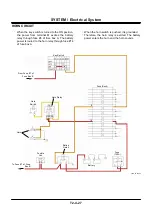
As the parking brake switch automatically returns
to neutral, the circuit from terminal E of the
parking brake switch to parking brake relay 2 is
blocked.
•
However, as a self-exciting circuit is formed in
parking brake relay 2, current keeps flowing to the
parking brake solenoid valve, and keeps the
released condition of the parking brake until the
key switch is turned to the OFF position or the
parking brake switch is turned to the ON position.
IMPORTANT:
The parking brake cannot be
released unless the engine is
running.
•
When the parking brake switch is turned to the
ON position, terminal A of the parking brake
switch is grounded, and parking brake relay 1 is
excited.
•
The power to terminal B of parking brake relay 2
and terminal B of the parking brake switch
through terminal D of parking brake relay 1 is
blocked.
•
Consequently, the parking brake is applied as
parking brake relay 2 and the parking brake
solenoid valve are unexcited.
Summary of Contents for ZW180
Page 1: ......
Page 2: ......
Page 8: ...4GDT 1 2 Blank ...
Page 10: ...GENERAL Specification T1 1 2 Blank ...
Page 38: ...GENERAL Component Specifications T1 3 14 Blank ...
Page 39: ...MEMO ...
Page 40: ...MEMO ...
Page 42: ...4GDT 2 2 Blank ...
Page 56: ...SYSTEM Control System T2 1 14 Blank ...
Page 82: ...SYSTEM Control System T2 1 40 Blank ...
Page 92: ...SYSTEM Control System T2 1 50 Blank ...
Page 106: ...SYSTEM Control System T2 1 64 Blank ...
Page 116: ...SYSTEM ECM System T2 2 10 Blank ...
Page 128: ...SYSTEM Hydraulic System T2 3 12 Blank ...
Page 147: ...SYSTEM Hydraulic System T2 3 31 Blank ...
Page 150: ...SYSTEM Hydraulic System T2 3 34 Blank ...
Page 184: ...SYSTEM Electric System T2 4 34 Blank ...
Page 185: ...MEMO ...
Page 186: ...MEMO ...
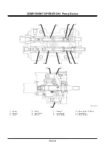
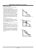
Page 195: ...COMPONENT OPERATION Pump Device T3 1 7 Blank ...
Page 212: ...COMPONENT OPERATION Control Valve T3 2 4 T4GB 03 02 003 1 2 3 4 5 7 8 9 10 11 7 6 ...
Page 214: ...COMPONENT OPERATION Control Valve T3 2 6 T4GB 03 02 003 1 2 3 4 5 7 8 9 10 11 7 6 ...
Page 226: ...COMPONENT OPERATION Control Valve T3 2 18 Blank ...
Page 232: ...COMPONENT OPERATION Control Valve T3 2 24 Blank ...
Page 248: ...COMPONENT OPERATION Steering Pilot Valve T3 4 6 Blank ...
Page 258: ...COMPONENT OPERATION Steering Valve T3 5 10 Blank ...
Page 274: ...COMPONENT OPERATION Pilot Valve T3 6 16 Blank ...
Page 282: ...COMPONENT OPERATION Pilot Valve T3 6 24 Blank ...
Page 299: ...COMPONENT OPERATION Ride Control Valve T3 8 5 Blank ...
Page 306: ...COMPONENT OPERATION Ride Control Valve T3 8 12 Blank ...
Page 348: ...COMPONENT OPERATION Drive Unit T3 9 42 Blank ...
Page 371: ...MEMO ...
Page 372: ...MEMO ...
Page 374: ......


