


INTRODUCTION
IN-02
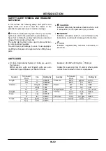
SAFETY ALERT SYMBOL AND HEADLINE
NOTATIONS
In this manual, the following safety alert symbol and
signal words are used to alert the reader to the
potential for personal injury of machine damage.
This is the safety alert symbol. When you see this
symbol, be alert to the potential for personal injury.
Never fail to follow the safety instructions prescribed
along with the safety alert symbol.
The safety alert symbol is also used to draw attention
to component/part weights.
To avoid injury and damage, be sure to use appropri-
ate lifting techniques and equipment when lifting heavy
parts.
•
CAUTION:
Indicated potentially hazardous situation which could,
if not avoided, result in personal injury or death.
•
IMPORTANT:
Indicates a situation which, if not conformed to the
instructions, could result in damage to the machine.
•
NOTE:
Indicates supplementary technical information or
know-how.
UNITS USED
•
SI Units (International System of Units) are used in
this manual.
MKSA system units and English units are also
indicated in parenthheses just behind SI units.
Example : 24.5 MPa (250 kgf/cm
2
, 3560 psi)
A table for conversion from SI units to other system
units is shown below for reference purposees.
Quantity
To Convert
From
Into Multiply
By
MPa kgf/cm
2
10.197
Pressure
MPa psi
145.0
kW PS
1.360
Power
kW HP
1.341
Temperature
°
C
°
F
°
C
×
1.8+32
km/h mph
0.6214
Velocity
min
-1
rpm
1.0
Flow rate
L/min
US gpm
0.2642
mL/rev
cc/rev
1.0
Quantity
To Convert
From
Into Multiply
By
mm in
0.03937
Length
mm ft
0.003281
L US
gal
0.2642
L US
qt
1.057
Volume
m
3
yd
3
1.308
Weight kg
lb
2.205
N kgf
0.10197
Force
N lbf
0.2248
N
⋅
m kgf
⋅
m 1.0197
Torque
N
⋅
m lbf
⋅
ft 0.7375
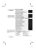
Summary of Contents for ZW180
Page 1: ......
Page 2: ......
Page 8: ...4GDT 1 2 Blank ...
Page 10: ...GENERAL Specification T1 1 2 Blank ...
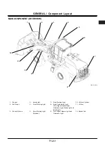
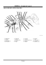
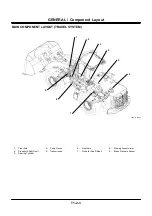
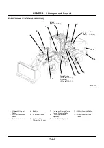
Page 38: ...GENERAL Component Specifications T1 3 14 Blank ...
Page 39: ...MEMO ...
Page 40: ...MEMO ...
Page 42: ...4GDT 2 2 Blank ...
Page 56: ...SYSTEM Control System T2 1 14 Blank ...
Page 82: ...SYSTEM Control System T2 1 40 Blank ...
Page 92: ...SYSTEM Control System T2 1 50 Blank ...
Page 106: ...SYSTEM Control System T2 1 64 Blank ...
Page 116: ...SYSTEM ECM System T2 2 10 Blank ...
Page 128: ...SYSTEM Hydraulic System T2 3 12 Blank ...
Page 147: ...SYSTEM Hydraulic System T2 3 31 Blank ...
Page 150: ...SYSTEM Hydraulic System T2 3 34 Blank ...
Page 184: ...SYSTEM Electric System T2 4 34 Blank ...
Page 185: ...MEMO ...
Page 186: ...MEMO ...
Page 195: ...COMPONENT OPERATION Pump Device T3 1 7 Blank ...
Page 212: ...COMPONENT OPERATION Control Valve T3 2 4 T4GB 03 02 003 1 2 3 4 5 7 8 9 10 11 7 6 ...
Page 214: ...COMPONENT OPERATION Control Valve T3 2 6 T4GB 03 02 003 1 2 3 4 5 7 8 9 10 11 7 6 ...
Page 226: ...COMPONENT OPERATION Control Valve T3 2 18 Blank ...
Page 232: ...COMPONENT OPERATION Control Valve T3 2 24 Blank ...
Page 248: ...COMPONENT OPERATION Steering Pilot Valve T3 4 6 Blank ...
Page 258: ...COMPONENT OPERATION Steering Valve T3 5 10 Blank ...
Page 274: ...COMPONENT OPERATION Pilot Valve T3 6 16 Blank ...
Page 282: ...COMPONENT OPERATION Pilot Valve T3 6 24 Blank ...
Page 299: ...COMPONENT OPERATION Ride Control Valve T3 8 5 Blank ...
Page 306: ...COMPONENT OPERATION Ride Control Valve T3 8 12 Blank ...
Page 348: ...COMPONENT OPERATION Drive Unit T3 9 42 Blank ...
Page 371: ...MEMO ...
Page 372: ...MEMO ...
Page 374: ......


