
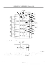

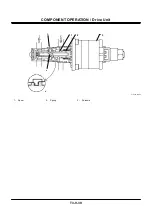

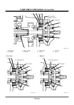


COMPONENT OPERATION / Axle
T3-10-8
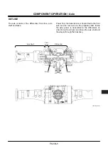
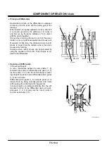
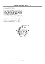
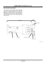
LIMITED SLIP DIFFERENTIAL (LSD)
(OPTIONAL)
The wheel loader must be operated on slippery ground
condition like sand and muddy soil. In places like
these, the tires can slip although the torque propor-
tioning differential (TPD) is installed. As rotation is
transmitted to the slipping tire and not to the tires con-
tacting the road, not only the funtion of the wheel
loader is worsened but the tire lives are shortened.
In order to avoid this, the limited slip differential (LSD)
provided with the differential movement restriction de-
vice in order to avoid different movement of the left
and right wheels is adopted. Driving force transmitted
to the left and right tires further changes.
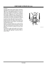
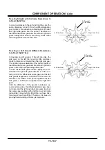
Operational Principle
LSD is so constructed that the clutch disc is inserted
between the pressure ring supporting the spider with
the cam and the case, which makes restriction of
different movement by keeping the tire speeds the
same by the resistances of the friction surfaces. The
variation of the driving force transmitted to the left
and right tires is made larger than TPD.
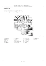
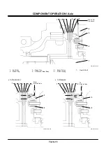
T4GB-03-10-003
Ring Gear
Pressure Ring
Side Gear
Pressure Plate
Clutch Disc
Case
Pinion Gear
Spider
Summary of Contents for ZW180
Page 1: ......
Page 2: ......
Page 8: ...4GDT 1 2 Blank ...
Page 10: ...GENERAL Specification T1 1 2 Blank ...
Page 38: ...GENERAL Component Specifications T1 3 14 Blank ...
Page 39: ...MEMO ...
Page 40: ...MEMO ...
Page 42: ...4GDT 2 2 Blank ...
Page 56: ...SYSTEM Control System T2 1 14 Blank ...
Page 82: ...SYSTEM Control System T2 1 40 Blank ...
Page 92: ...SYSTEM Control System T2 1 50 Blank ...
Page 106: ...SYSTEM Control System T2 1 64 Blank ...
Page 116: ...SYSTEM ECM System T2 2 10 Blank ...
Page 128: ...SYSTEM Hydraulic System T2 3 12 Blank ...
Page 147: ...SYSTEM Hydraulic System T2 3 31 Blank ...
Page 150: ...SYSTEM Hydraulic System T2 3 34 Blank ...
Page 184: ...SYSTEM Electric System T2 4 34 Blank ...
Page 185: ...MEMO ...
Page 186: ...MEMO ...
Page 195: ...COMPONENT OPERATION Pump Device T3 1 7 Blank ...
Page 212: ...COMPONENT OPERATION Control Valve T3 2 4 T4GB 03 02 003 1 2 3 4 5 7 8 9 10 11 7 6 ...
Page 214: ...COMPONENT OPERATION Control Valve T3 2 6 T4GB 03 02 003 1 2 3 4 5 7 8 9 10 11 7 6 ...
Page 226: ...COMPONENT OPERATION Control Valve T3 2 18 Blank ...
Page 232: ...COMPONENT OPERATION Control Valve T3 2 24 Blank ...
Page 248: ...COMPONENT OPERATION Steering Pilot Valve T3 4 6 Blank ...
Page 258: ...COMPONENT OPERATION Steering Valve T3 5 10 Blank ...
Page 274: ...COMPONENT OPERATION Pilot Valve T3 6 16 Blank ...
Page 282: ...COMPONENT OPERATION Pilot Valve T3 6 24 Blank ...
Page 299: ...COMPONENT OPERATION Ride Control Valve T3 8 5 Blank ...
Page 306: ...COMPONENT OPERATION Ride Control Valve T3 8 12 Blank ...
Page 348: ...COMPONENT OPERATION Drive Unit T3 9 42 Blank ...
Page 371: ...MEMO ...
Page 372: ...MEMO ...
Page 374: ......


