
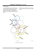
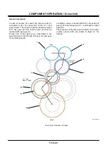
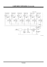
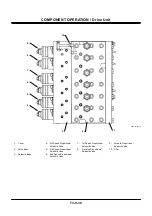


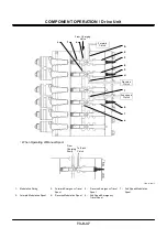

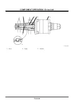


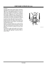

COMPONENT OPERATION / Drive Unit
T3-9-34
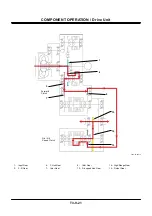
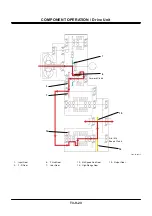
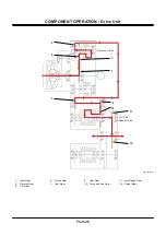
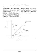
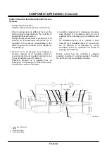
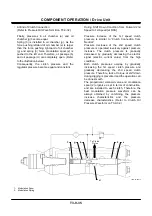
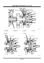
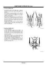
Clutch Connection from Neutral (Clutch Pressure
Increase)
•
During Clutch Connection
(Refer to Oil Pressure Waveform A on T3-9-32.)
When the transmission is shifted by the lever, the
electric signal is transmitted from the controller to
proportional solenoid valve (1).
During oil pressure waveform A, pressure oil to oil
passage (a) of proportional solenoid valve (1) is
regulated to the pressure corresponding to the
electric signal of the controller, and is supplied to
oil passage (c).
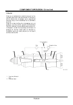
1. Pressure oil to oil passage (c) is supplied to
pressure chamber (e) of modulation spool (2),
overcomes the force of modulation spring (3), and
moves modulation spool (2) leftward.
Therefore, pressure oil is supplied from oil
passage (b) to oil passage (d) of the clutch piston,
and the clutch pressure increases.
2. In addition, pressure oil to oil passage (d) passes
back chamber (f) of modulation spool (2), and is
supplied to back chamber (g) of modulation spool
(2).
As modulation spring (3) is installed in back
chamber (g) of modulation spool (2), it overcomes
the oil pressure in oil passage (d), moves
modulation spool (2) rightward and closes oil
passage (d) temporarily.
Electric current from the controller is enlarged
gradually, and steps 1 and 2are repeated. Therefore,
the clutch oil pressure gradually increases.
T4GD-03-09-014
1 - Proportional Solenoid
Valve
2 - Modulation Spool
3 - Modulation Spring
d
f
To Clutch
Piston
g
3
1
c
a
b
e
2
Summary of Contents for ZW180
Page 1: ......
Page 2: ......
Page 8: ...4GDT 1 2 Blank ...
Page 10: ...GENERAL Specification T1 1 2 Blank ...
Page 38: ...GENERAL Component Specifications T1 3 14 Blank ...
Page 39: ...MEMO ...
Page 40: ...MEMO ...
Page 42: ...4GDT 2 2 Blank ...
Page 56: ...SYSTEM Control System T2 1 14 Blank ...
Page 82: ...SYSTEM Control System T2 1 40 Blank ...
Page 92: ...SYSTEM Control System T2 1 50 Blank ...
Page 106: ...SYSTEM Control System T2 1 64 Blank ...
Page 116: ...SYSTEM ECM System T2 2 10 Blank ...
Page 128: ...SYSTEM Hydraulic System T2 3 12 Blank ...
Page 147: ...SYSTEM Hydraulic System T2 3 31 Blank ...
Page 150: ...SYSTEM Hydraulic System T2 3 34 Blank ...
Page 184: ...SYSTEM Electric System T2 4 34 Blank ...
Page 185: ...MEMO ...
Page 186: ...MEMO ...
Page 195: ...COMPONENT OPERATION Pump Device T3 1 7 Blank ...
Page 212: ...COMPONENT OPERATION Control Valve T3 2 4 T4GB 03 02 003 1 2 3 4 5 7 8 9 10 11 7 6 ...
Page 214: ...COMPONENT OPERATION Control Valve T3 2 6 T4GB 03 02 003 1 2 3 4 5 7 8 9 10 11 7 6 ...
Page 226: ...COMPONENT OPERATION Control Valve T3 2 18 Blank ...
Page 232: ...COMPONENT OPERATION Control Valve T3 2 24 Blank ...
Page 248: ...COMPONENT OPERATION Steering Pilot Valve T3 4 6 Blank ...
Page 258: ...COMPONENT OPERATION Steering Valve T3 5 10 Blank ...
Page 274: ...COMPONENT OPERATION Pilot Valve T3 6 16 Blank ...
Page 282: ...COMPONENT OPERATION Pilot Valve T3 6 24 Blank ...
Page 299: ...COMPONENT OPERATION Ride Control Valve T3 8 5 Blank ...
Page 306: ...COMPONENT OPERATION Ride Control Valve T3 8 12 Blank ...
Page 348: ...COMPONENT OPERATION Drive Unit T3 9 42 Blank ...
Page 371: ...MEMO ...
Page 372: ...MEMO ...
Page 374: ......


