COMPONENT OPERATION / Axle
T3-10-4
•
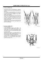
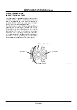
Principle of Differential
Operational principle of the differential is explained
comparing it to the racks and the pinion gear in the
drawing.
When load W is equally applied to racks A and B, if
C is moved upward by the distance of H, racks A
and B move by the same distance of H in unison
with the pinion together.
If moved by removing the load to rack B, the pinion
rotates on rack A (with load applied) and moves rack
B upward. At this time, the distance where rack B
moves is longer than the distance where the pinion
moves while rotating.
Distance where rack B moves can be calculated by
using the equation of H
+
H
=
2H. This principle is ap-
plied to the differential.
•
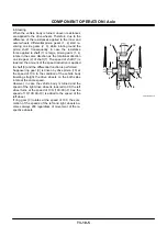
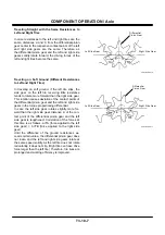
Operation of Differential
In Traveling Straight
In case resistances applied to axle shafts (7, 8)
connected by spline to differential side gears (2, 3)
are the same, or in case the vehicle body is travel-
ing straight on plane roads, differential pinion gears
(1, 4) do not rotate.
Differential pinion gears (1, 4) and side gears (2, 3)
remain fixed by being mutually geared, and rotate
with housing (6) connected with ring gear (9).
In case all parts are rotating solidly like this, the dif-
ferential function of the differential does not work,
and gears (1, 2, 3, 4) play only the role of joints to
connect axle shafts (7, 8).
T202-03-05-006
T487-03-06-014
W
H
H
H
2H
C
C
Rack (B)
Pinion
Pinion
Rack (A)
W
W
Rack (B)
Rack (A)
10
1
7
2
6
4
3
8
9
Summary of Contents for ZW180
Page 1: ......
Page 2: ......
Page 8: ...4GDT 1 2 Blank ...
Page 10: ...GENERAL Specification T1 1 2 Blank ...
Page 38: ...GENERAL Component Specifications T1 3 14 Blank ...
Page 39: ...MEMO ...
Page 40: ...MEMO ...
Page 42: ...4GDT 2 2 Blank ...
Page 56: ...SYSTEM Control System T2 1 14 Blank ...
Page 82: ...SYSTEM Control System T2 1 40 Blank ...
Page 92: ...SYSTEM Control System T2 1 50 Blank ...
Page 106: ...SYSTEM Control System T2 1 64 Blank ...
Page 116: ...SYSTEM ECM System T2 2 10 Blank ...
Page 128: ...SYSTEM Hydraulic System T2 3 12 Blank ...
Page 147: ...SYSTEM Hydraulic System T2 3 31 Blank ...
Page 150: ...SYSTEM Hydraulic System T2 3 34 Blank ...
Page 184: ...SYSTEM Electric System T2 4 34 Blank ...
Page 185: ...MEMO ...
Page 186: ...MEMO ...
Page 195: ...COMPONENT OPERATION Pump Device T3 1 7 Blank ...
Page 212: ...COMPONENT OPERATION Control Valve T3 2 4 T4GB 03 02 003 1 2 3 4 5 7 8 9 10 11 7 6 ...
Page 214: ...COMPONENT OPERATION Control Valve T3 2 6 T4GB 03 02 003 1 2 3 4 5 7 8 9 10 11 7 6 ...
Page 226: ...COMPONENT OPERATION Control Valve T3 2 18 Blank ...
Page 232: ...COMPONENT OPERATION Control Valve T3 2 24 Blank ...
Page 248: ...COMPONENT OPERATION Steering Pilot Valve T3 4 6 Blank ...
Page 258: ...COMPONENT OPERATION Steering Valve T3 5 10 Blank ...
Page 274: ...COMPONENT OPERATION Pilot Valve T3 6 16 Blank ...
Page 282: ...COMPONENT OPERATION Pilot Valve T3 6 24 Blank ...
Page 299: ...COMPONENT OPERATION Ride Control Valve T3 8 5 Blank ...
Page 306: ...COMPONENT OPERATION Ride Control Valve T3 8 12 Blank ...
Page 348: ...COMPONENT OPERATION Drive Unit T3 9 42 Blank ...
Page 371: ...MEMO ...
Page 372: ...MEMO ...
Page 374: ......

