


SYSTEM / Hydraulic System
T2-3-32
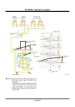
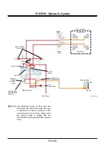
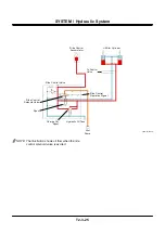
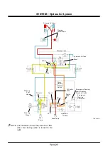
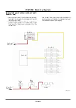
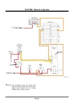
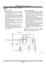
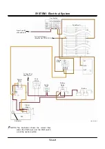
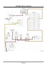
HYDRAULIC DRIVE FAN CIRCUIT
(Refer to the COMPONET OPERATION / Others
group.)
(Refer to the COMPONET OPERATION / Hydraulic
Fan Motor group.)
•
Pressure oil from the fan pump flows to the fan
motor through the flow control valve and the
reverse rotation spool.
•
Current corresponding to the hydraulic oil
temperature is sent from MC to the flow control
solenoid valve.
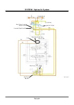
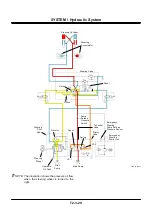
•
Pressure oil is supplied to the flow control valve
end in response to the stroke when the flow
adjusting solenoid valve is excited.
•
When the flow rate control valve is operated,
pressure oil from the fan pump to the fan motor is
restricted, and speed of the fan motor is
controlled.
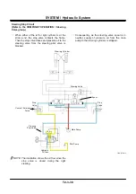
•
When the fan reverse rotation switch is turned ON,
current flows from MC to the reverse rotation
control solenoid valve.
•
When the reverse rotation control solenoid valve
is operated, pressure oil is supplied to the reverse
rotation spool end.
•
When the reverse rotation spool is shifted, the
inlet port of pressure oil supplied to the fan motor
is shifted, and the fan motor rotates reversely.
Summary of Contents for ZW180
Page 1: ......
Page 2: ......
Page 8: ...4GDT 1 2 Blank ...
Page 10: ...GENERAL Specification T1 1 2 Blank ...
Page 38: ...GENERAL Component Specifications T1 3 14 Blank ...
Page 39: ...MEMO ...
Page 40: ...MEMO ...
Page 42: ...4GDT 2 2 Blank ...
Page 56: ...SYSTEM Control System T2 1 14 Blank ...
Page 82: ...SYSTEM Control System T2 1 40 Blank ...
Page 92: ...SYSTEM Control System T2 1 50 Blank ...
Page 106: ...SYSTEM Control System T2 1 64 Blank ...
Page 116: ...SYSTEM ECM System T2 2 10 Blank ...
Page 128: ...SYSTEM Hydraulic System T2 3 12 Blank ...
Page 147: ...SYSTEM Hydraulic System T2 3 31 Blank ...
Page 150: ...SYSTEM Hydraulic System T2 3 34 Blank ...
Page 184: ...SYSTEM Electric System T2 4 34 Blank ...
Page 185: ...MEMO ...
Page 186: ...MEMO ...
Page 195: ...COMPONENT OPERATION Pump Device T3 1 7 Blank ...
Page 212: ...COMPONENT OPERATION Control Valve T3 2 4 T4GB 03 02 003 1 2 3 4 5 7 8 9 10 11 7 6 ...
Page 214: ...COMPONENT OPERATION Control Valve T3 2 6 T4GB 03 02 003 1 2 3 4 5 7 8 9 10 11 7 6 ...
Page 226: ...COMPONENT OPERATION Control Valve T3 2 18 Blank ...
Page 232: ...COMPONENT OPERATION Control Valve T3 2 24 Blank ...
Page 248: ...COMPONENT OPERATION Steering Pilot Valve T3 4 6 Blank ...
Page 258: ...COMPONENT OPERATION Steering Valve T3 5 10 Blank ...
Page 274: ...COMPONENT OPERATION Pilot Valve T3 6 16 Blank ...
Page 282: ...COMPONENT OPERATION Pilot Valve T3 6 24 Blank ...
Page 299: ...COMPONENT OPERATION Ride Control Valve T3 8 5 Blank ...
Page 306: ...COMPONENT OPERATION Ride Control Valve T3 8 12 Blank ...
Page 348: ...COMPONENT OPERATION Drive Unit T3 9 42 Blank ...
Page 371: ...MEMO ...
Page 372: ...MEMO ...
Page 374: ......


