


COMPONENT OPERATION / Pump Device
T3-1-8
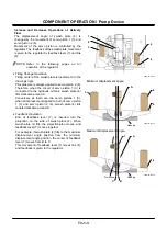
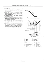
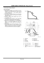
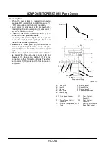
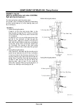
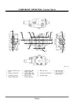
Control by Pump Control Pressure
Decreasing Flow
1. When the control lever stroke is reduced,
pressure difference (difference between pressure
Pi1 and Pi2) arising at the flow control valve in the
control valve is larger.
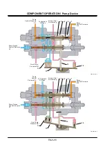
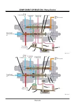
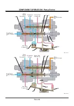
2. Pump control pressure Pi1 pushes spool 1 (3)
and spool 1 (3) moves toward the arrow.
3. Therefore, primary pilot pressure Pg is led to
servo piston 1 (10).
4. As there are two servo pistons 1 (10), swash plate
(11) tilts toward the flow decreasing direction.
5. Movement of swash plate (11) is transmitted to
sleeve 1 (2) through feedback lever link (13).
Sleeve 1 (2) moves toward the movement of
spool 1 (3).
6. Pilot primary pressure Pg to servo piston 1 (10) is
blocked when sleeve 1 (2) has moved the same
distance as spool 1 (3). Therefore, servo piston 1
(10) stops and the flow decrease is completed.
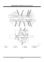
T4GB-03-01-006
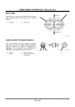
1 - Spring
10 - Servo Piston 1
2 - Sleeve 1
11 - Swash Plate
3 - Spool 1
12 - Servo Piston 2
4 - Piston
13 - Feedback Lever Link
Pd1 - Own Pump Pressure
Pi1 - Pump Control
Pressure 1
ST -
Torque Control
Pressure
Pi2 - Pump Control
Pressure 2
T -
Returning to Hydraulic
Oil Tank
Pg -
Primary Pilot Pressure
(From Pilot Pump)
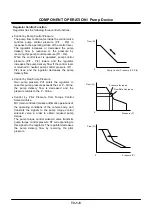
Flow (Q)
Pump Control Pressure (Pi1-Pi2)
0
3
2
1
4
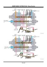
Pi1
T
Air
Vent
Pi2
Pg
T
ST
Pd1
T
Increase
Decrease
Displacement Angle
10
12
13
Summary of Contents for ZW180
Page 1: ......
Page 2: ......
Page 8: ...4GDT 1 2 Blank ...
Page 10: ...GENERAL Specification T1 1 2 Blank ...
Page 38: ...GENERAL Component Specifications T1 3 14 Blank ...
Page 39: ...MEMO ...
Page 40: ...MEMO ...
Page 42: ...4GDT 2 2 Blank ...
Page 56: ...SYSTEM Control System T2 1 14 Blank ...
Page 82: ...SYSTEM Control System T2 1 40 Blank ...
Page 92: ...SYSTEM Control System T2 1 50 Blank ...
Page 106: ...SYSTEM Control System T2 1 64 Blank ...
Page 116: ...SYSTEM ECM System T2 2 10 Blank ...
Page 128: ...SYSTEM Hydraulic System T2 3 12 Blank ...
Page 147: ...SYSTEM Hydraulic System T2 3 31 Blank ...
Page 150: ...SYSTEM Hydraulic System T2 3 34 Blank ...
Page 184: ...SYSTEM Electric System T2 4 34 Blank ...
Page 185: ...MEMO ...
Page 186: ...MEMO ...
Page 195: ...COMPONENT OPERATION Pump Device T3 1 7 Blank ...
Page 212: ...COMPONENT OPERATION Control Valve T3 2 4 T4GB 03 02 003 1 2 3 4 5 7 8 9 10 11 7 6 ...
Page 214: ...COMPONENT OPERATION Control Valve T3 2 6 T4GB 03 02 003 1 2 3 4 5 7 8 9 10 11 7 6 ...
Page 226: ...COMPONENT OPERATION Control Valve T3 2 18 Blank ...
Page 232: ...COMPONENT OPERATION Control Valve T3 2 24 Blank ...
Page 248: ...COMPONENT OPERATION Steering Pilot Valve T3 4 6 Blank ...
Page 258: ...COMPONENT OPERATION Steering Valve T3 5 10 Blank ...
Page 274: ...COMPONENT OPERATION Pilot Valve T3 6 16 Blank ...
Page 282: ...COMPONENT OPERATION Pilot Valve T3 6 24 Blank ...
Page 299: ...COMPONENT OPERATION Ride Control Valve T3 8 5 Blank ...
Page 306: ...COMPONENT OPERATION Ride Control Valve T3 8 12 Blank ...
Page 348: ...COMPONENT OPERATION Drive Unit T3 9 42 Blank ...
Page 371: ...MEMO ...
Page 372: ...MEMO ...
Page 374: ......


