COMPONENT OPERATION / Pump Device
T3-1-12
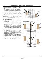
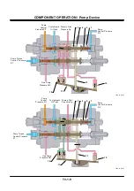
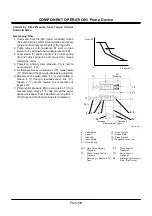
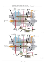
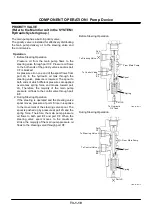
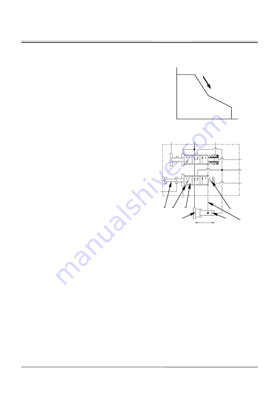
Control by Own Pump Pressure
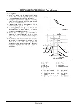
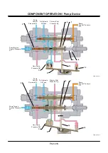
Decreasing Flow
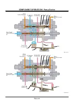
1. When load is applied to the pump due to any
operation, own pump pressure Pd1 rises. (Pump
control pressure (Pi1 - Pi2) remains lowered
during an operation.)
2. Load piston (5) pushes spool 2 (6), inner spring
(8) and outer spring (9), and spool 2 (6) moves
toward the arrow.
3. Therefore, primary pilot pressure Pg is led to
servo piston 1 (10).
4. As there are two servo pistons 1 (10), swash plate
(11) tilts toward the flow decreasing direction.
5. Movement of swash plate (11) is transmitted to
sleeve 2 (7) through feedback lever link (13).
Sleeve 2 (7) moves toward the movement of
spool 2 (6).
6. Primary pilot pressure Pg to servo piston 1 (10) is
blocked when sleeve 2 (7) has moved the same
distance as spool 2 (6). Therefore, servo piston 1
(10) stops and the flow decrease is completed.
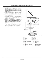
T4GB-03-01-006
5 - Load Piston
10 - Servo Piston 1
6 - Spool 2
11 - Swash Plate
7 - Sleeve 2
12 - Servo Piston 2
8 - Inner Spring
13 - Feedback Lever Link
9 - Outer Spring
Pd1 - Own Pump Pressure
Pi1 - Pump Control
Pressure 1
ST - Pump Torque Control
Pressure
Pi2 - Pump Control
Pressure 2
T -
Returning to Hydraulic Oil
Tank
Pg -
Primary Pilot Pressure
(From Pilot Pump)
Flow (Q)
Pressure (P)
0
5
Pi1
T
Air
Bleeding
Pi2
Pg
T
ST
Pd1
T
Increase
Decrease
Displacement Angle
7
6
10
12
8, 9
13
Summary of Contents for ZW180
Page 1: ......
Page 2: ......
Page 8: ...4GDT 1 2 Blank ...
Page 10: ...GENERAL Specification T1 1 2 Blank ...
Page 38: ...GENERAL Component Specifications T1 3 14 Blank ...
Page 39: ...MEMO ...
Page 40: ...MEMO ...
Page 42: ...4GDT 2 2 Blank ...
Page 56: ...SYSTEM Control System T2 1 14 Blank ...
Page 82: ...SYSTEM Control System T2 1 40 Blank ...
Page 92: ...SYSTEM Control System T2 1 50 Blank ...
Page 106: ...SYSTEM Control System T2 1 64 Blank ...
Page 116: ...SYSTEM ECM System T2 2 10 Blank ...
Page 128: ...SYSTEM Hydraulic System T2 3 12 Blank ...
Page 147: ...SYSTEM Hydraulic System T2 3 31 Blank ...
Page 150: ...SYSTEM Hydraulic System T2 3 34 Blank ...
Page 184: ...SYSTEM Electric System T2 4 34 Blank ...
Page 185: ...MEMO ...
Page 186: ...MEMO ...
Page 195: ...COMPONENT OPERATION Pump Device T3 1 7 Blank ...
Page 212: ...COMPONENT OPERATION Control Valve T3 2 4 T4GB 03 02 003 1 2 3 4 5 7 8 9 10 11 7 6 ...
Page 214: ...COMPONENT OPERATION Control Valve T3 2 6 T4GB 03 02 003 1 2 3 4 5 7 8 9 10 11 7 6 ...
Page 226: ...COMPONENT OPERATION Control Valve T3 2 18 Blank ...
Page 232: ...COMPONENT OPERATION Control Valve T3 2 24 Blank ...
Page 248: ...COMPONENT OPERATION Steering Pilot Valve T3 4 6 Blank ...
Page 258: ...COMPONENT OPERATION Steering Valve T3 5 10 Blank ...
Page 274: ...COMPONENT OPERATION Pilot Valve T3 6 16 Blank ...
Page 282: ...COMPONENT OPERATION Pilot Valve T3 6 24 Blank ...
Page 299: ...COMPONENT OPERATION Ride Control Valve T3 8 5 Blank ...
Page 306: ...COMPONENT OPERATION Ride Control Valve T3 8 12 Blank ...
Page 348: ...COMPONENT OPERATION Drive Unit T3 9 42 Blank ...
Page 371: ...MEMO ...
Page 372: ...MEMO ...
Page 374: ......


