


SYSTEM / Control System
T2-1-56
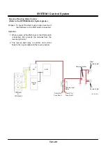
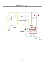
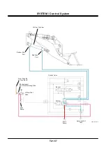
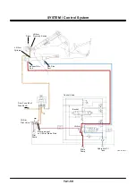
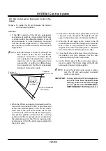
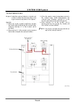
Lift Arm Float Control
Purpose: Free to raise and lower the lift arm in re-
sponse to the external force in order to re-
move snow and clean road.
Operation:
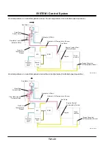
1. When the lift arm control on lever is moved to the
floating position (farther position than the lift arm
lowering position), the lift arm control lever is re-
tained by the electromagnet on the lift arm lower-
ing side, and pressure oil from the pilot valve
moves the lift arm spool in the control valve to the
floating position (farthest right position).
NOTE: When the engine is running, the electro-
magnet on the lift arm lowering side is al-
ways excited by current from fuse #6 of
fuse box B.
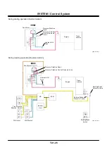
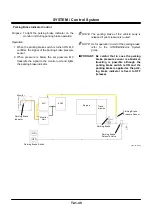
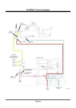
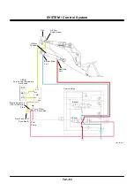
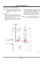
2. Pressure oil from the main pump is blocked by the
lift arm spool, and the ports on the rod side and
the bottom side of the lift arm cylinder are con-
nected, to the tank port through the lift arm spool.
As the both ports of the lift arm cylinder have the
same pressure as the hydraulic oil tank, the lift
arm cylinder is not restricted and the lift arm can
move in response to the external force.
3. The lift arm control lever returns to neutral if
pulled more strongly than the magnetic force of
the electromagnet. As the lift arm spool in the
control valve also returns to neutral, the lift arm
float control is released.
Summary of Contents for ZW180
Page 1: ......
Page 2: ......
Page 8: ...4GDT 1 2 Blank ...
Page 10: ...GENERAL Specification T1 1 2 Blank ...
Page 38: ...GENERAL Component Specifications T1 3 14 Blank ...
Page 39: ...MEMO ...
Page 40: ...MEMO ...
Page 42: ...4GDT 2 2 Blank ...
Page 56: ...SYSTEM Control System T2 1 14 Blank ...
Page 82: ...SYSTEM Control System T2 1 40 Blank ...
Page 92: ...SYSTEM Control System T2 1 50 Blank ...
Page 106: ...SYSTEM Control System T2 1 64 Blank ...
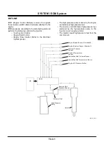
Page 116: ...SYSTEM ECM System T2 2 10 Blank ...
Page 128: ...SYSTEM Hydraulic System T2 3 12 Blank ...
Page 147: ...SYSTEM Hydraulic System T2 3 31 Blank ...
Page 150: ...SYSTEM Hydraulic System T2 3 34 Blank ...
Page 184: ...SYSTEM Electric System T2 4 34 Blank ...
Page 185: ...MEMO ...
Page 186: ...MEMO ...
Page 195: ...COMPONENT OPERATION Pump Device T3 1 7 Blank ...
Page 212: ...COMPONENT OPERATION Control Valve T3 2 4 T4GB 03 02 003 1 2 3 4 5 7 8 9 10 11 7 6 ...
Page 214: ...COMPONENT OPERATION Control Valve T3 2 6 T4GB 03 02 003 1 2 3 4 5 7 8 9 10 11 7 6 ...
Page 226: ...COMPONENT OPERATION Control Valve T3 2 18 Blank ...
Page 232: ...COMPONENT OPERATION Control Valve T3 2 24 Blank ...
Page 248: ...COMPONENT OPERATION Steering Pilot Valve T3 4 6 Blank ...
Page 258: ...COMPONENT OPERATION Steering Valve T3 5 10 Blank ...
Page 274: ...COMPONENT OPERATION Pilot Valve T3 6 16 Blank ...
Page 282: ...COMPONENT OPERATION Pilot Valve T3 6 24 Blank ...
Page 299: ...COMPONENT OPERATION Ride Control Valve T3 8 5 Blank ...
Page 306: ...COMPONENT OPERATION Ride Control Valve T3 8 12 Blank ...
Page 348: ...COMPONENT OPERATION Drive Unit T3 9 42 Blank ...
Page 371: ...MEMO ...
Page 372: ...MEMO ...
Page 374: ......


