


SYSTEM / Control System
T2-1-1
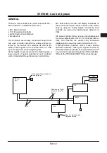
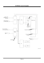
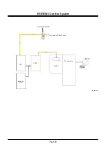
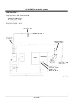
GENERAL
There are four controllers as shown below with MC –
Main Controller – installed at their center.
•
MC: Main Controller
•
ICF: Information Controller
•
ECM: Engine Control Module
•
Monitor Unit
The controllers are mutually connected through CAN,
and each controller uploads the analog signals de-
tected by the sensors and switches as well as the
analog output signals to the solenoid valves on CAN
by converting them into the digital signals.
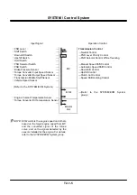
As the signals are processed into the digital signals, a
large amount of signals detected by each controller
can be transmitted through few wires in a shirt time.
MC, ECM and the monitor unit display indications on
the monitors and make various controls of the vehicle
body by using the analog signals received by each
controller as well as the digital signals detected on
CAN.
ICF stores machine history, receives the digital signals
for various adjustments from Dr. ZX, transmits them to
CAN, and transmits the vehicle body information
(digital signal) received by each controller to Dr. ZX.
A GPS-provision (optional) vehicle makes location
arithmetic operation, utilising the signals received by
artificial satellites and transmits body information to the
e-service host computer through the artificial satellites.
(Refer to the TROUBLESHOOTING/e-wheel group.)
ECM
Monitor
Unit
ICF
CAN
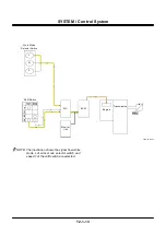
Sensors, Switches and
Solenoid Valves
S
S
S
Dr. ZX
MC
GPS
Receipt and Transmission by
Analog Signal
Receipt and Trans-
mission by Digital
Signal
Summary of Contents for ZW180
Page 1: ......
Page 2: ......
Page 8: ...4GDT 1 2 Blank ...
Page 10: ...GENERAL Specification T1 1 2 Blank ...
Page 38: ...GENERAL Component Specifications T1 3 14 Blank ...
Page 39: ...MEMO ...
Page 40: ...MEMO ...
Page 42: ...4GDT 2 2 Blank ...
Page 56: ...SYSTEM Control System T2 1 14 Blank ...
Page 82: ...SYSTEM Control System T2 1 40 Blank ...
Page 92: ...SYSTEM Control System T2 1 50 Blank ...
Page 106: ...SYSTEM Control System T2 1 64 Blank ...
Page 116: ...SYSTEM ECM System T2 2 10 Blank ...
Page 128: ...SYSTEM Hydraulic System T2 3 12 Blank ...
Page 147: ...SYSTEM Hydraulic System T2 3 31 Blank ...
Page 150: ...SYSTEM Hydraulic System T2 3 34 Blank ...
Page 184: ...SYSTEM Electric System T2 4 34 Blank ...
Page 185: ...MEMO ...
Page 186: ...MEMO ...
Page 195: ...COMPONENT OPERATION Pump Device T3 1 7 Blank ...
Page 212: ...COMPONENT OPERATION Control Valve T3 2 4 T4GB 03 02 003 1 2 3 4 5 7 8 9 10 11 7 6 ...
Page 214: ...COMPONENT OPERATION Control Valve T3 2 6 T4GB 03 02 003 1 2 3 4 5 7 8 9 10 11 7 6 ...
Page 226: ...COMPONENT OPERATION Control Valve T3 2 18 Blank ...
Page 232: ...COMPONENT OPERATION Control Valve T3 2 24 Blank ...
Page 248: ...COMPONENT OPERATION Steering Pilot Valve T3 4 6 Blank ...
Page 258: ...COMPONENT OPERATION Steering Valve T3 5 10 Blank ...
Page 274: ...COMPONENT OPERATION Pilot Valve T3 6 16 Blank ...
Page 282: ...COMPONENT OPERATION Pilot Valve T3 6 24 Blank ...
Page 299: ...COMPONENT OPERATION Ride Control Valve T3 8 5 Blank ...
Page 306: ...COMPONENT OPERATION Ride Control Valve T3 8 12 Blank ...
Page 348: ...COMPONENT OPERATION Drive Unit T3 9 42 Blank ...
Page 371: ...MEMO ...
Page 372: ...MEMO ...
Page 374: ......


