background image

Machine
Serial Number

The information and illustrations in this manual have
been approved as accurate at the time of printing.
However, the manual may contain information on options
not present on your loader.  The right is reserved by
Barko Hydraulics,LLC to make changes and
improvements in it's product at anytime without notice
or obligation.

BARKO

BARKO

BARKO

BARKO

BARKO

LOADERS

LOADERS

LOADERS

LOADERS

LOADERS

SERVICE MANUAL

SERVICE MANUAL

SERVICE MANUAL

SERVICE MANUAL

SERVICE MANUAL

080699

275B  SER-ERS

275B  SER-ERS

275B  SER-ERS

275B  SER-ERS

275B  SER-ERS

(Stationary Electric Remote with Electric Remote Station)

(Stationary Electric Remote with Electric Remote Station)

(Stationary Electric Remote with Electric Remote Station)

(Stationary Electric Remote with Electric Remote Station)

(Stationary Electric Remote with Electric Remote Station)

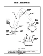
NOTE: The Grapple Service and Installation Information is not included in this manual.  See separate

Grapple Service and Installation manual which accompanies all grapples from the factory.

BARKO

BARKO

BARKO

BARKO

BARKO

HYDRAULICS,

HYDRAULICS,

HYDRAULICS,

HYDRAULICS,

HYDRAULICS,

LLC

LLC

LLC

LLC

LLC

mailing: PO Box 16227, Duluth, MN  55816     shipping: 1 Banks Avenue, Superior, WI  54880
phone: 715-392-5641     fax: 715-392-3931
website: www.barko.com     email: [email protected]

OPERATORS

OPERATORS

OPERATORS

OPERATORS

OPERATORS: 800-00023          PARTS

PARTS

PARTS

PARTS

PARTS: 800-00084         SERVICE

SERVICE

SERVICE

SERVICE

SERVICE: 800-00152

Содержание BARKO LOADERS 275B SER-ERS

Страница 1: ...nary Electric Remote with Electric Remote Station Stationary Electric Remote with Electric Remote Station Stationary Electric Remote with Electric Remote Station Stationary Electric Remote with Electr...

Страница 2: ...Hydraulic System B Hydraulic System B Hydraulic System B Hydraulic System 23 23 23 23 23 Hydraulic Schematics 24 Hydraulic Pressure Settings 25 Hydraulic Reservoir Maintenance 26 Hydraulic Oil Filter...

Страница 3: ...page 3 page 3 page 3 page 3 page 3 275BSER 800 00152 Introduction Introduction Introduction Introduction Introduction...

Страница 4: ...industrial accidents each year A professional operator should also be familiar with the information contained in other applicable sources such as American National Standards SAE OSHA etc ADDITIONALINF...

Страница 5: ...ition Ignition Key Switch Key Switch Key Switch Key Switch Key Switch Power On Power On Power On Power On Power On Accessory Accessory Accessory Accessory Accessory Power Off Power Off Power Off Power...

Страница 6: ...evels render each and all Barko warranties null and void and constitute an obvious misuse and abuse of our product WARNING WARNING WARNING WARNING WARNING MODEL 275B MODEL 275B MODEL 275B MODEL 275B M...

Страница 7: ...BARKO within ten 10 days from the date on which the defect was discovered and any claim submitted within thirty 30 days after repair work is completed BARKO warranty does not cover 1 Defects damage o...

Страница 8: ...e lowered to When machine is not operating or when leaving cab boom and attachment must be lowered to When machine is not operating or when leaving cab boom and attachment must be lowered to When mach...

Страница 9: ...re leaving cab If necessary to work engine before leaving cab If necessary to work on machine with lifted boom securely support on machine with lifted boom securely support on machine with lifted boom...

Страница 10: ...m such precautions to protect personnel from such precautions to protect personnel from such precautions to protect personnel from such precautions to protect personnel from such injury Personnel shou...

Страница 11: ...Always be pump or engine is not operating Always be pump or engine is not operating Always be certain that boom and attachment are properly certain that boom and attachment are properly certain that b...

Страница 12: ...gainst human skin Serious compressed air against human skin Serious compressed air against human skin Serious compressed air against human skin Serious compressed air against human skin Serious injury...

Страница 13: ...in any way attachment so that they cannot move or fall in any way attachment so that they cannot move or fall in any way attachment so that they cannot move or fall in any way Stick Boom Stick Boom S...

Страница 14: ...Always clean fluid spills Clean the machine and disconnect power before doing any welding Cover rubber hoses and other flammable parts Never ground arc welder or electrical accessories through turnta...

Страница 15: ...00152 Maintenance Maintenance Maintenance Maintenance Maintenance A PREVENTIVE MAINTENANCE A PREVENTIVE MAINTENANCE A PREVENTIVE MAINTENANCE A PREVENTIVE MAINTENANCE A PREVENTIVE MAINTENANCE Maintena...

Страница 16: ...and may cause structural damage void the warranty and may cause structural damage void the warranty and may cause structural damage void the warranty and may cause structural damage void the warranty...

Страница 17: ...lways needed for Safety glasses or goggles are always needed for Safety glasses or goggles are always needed for eye protection from electric arcs from shorts or eye protection from electric arcs from...

Страница 18: ...rol Lever Linkage if applicable Lubricate Bolts Nuts Bolts Nuts Bolts Nuts Bolts Nuts Bolts Nuts Check for proper torque every 50 hours Retorque if necessary Hydraulic Collector Hydraulic Collector Hy...

Страница 19: ...a daily basis 10 10 10 10 10 WARNING WARNING WARNING WARNING WARNING Boom is shown in lifted operating position Always shut down the machine and lower Boom is shown in lifted operating position Alway...

Страница 20: ...ety goggles visible Use a piece of cardboard or wood to find leaks but do not use bare hand Wear safety goggles visible Use a piece of cardboard or wood to find leaks but do not use bare hand Wear saf...

Страница 21: ...x Mounting Bolts 310 Ft Lbs Turntable Bearing Bolts 310 Ft Lbs Grapple Bearing Bolts continuous rotation grapples only 127 Ft Lbs Grapple Motor Mounting Bolts 64 Ft Lbs WARNING WARNING WARNING WARNING...

Страница 22: ...ON HEAD GRADE 9 HEAD GRADE 9 HEAD GRADE 9 HEAD GRADE 9 HEAD GRADE 9 BOW MALLOY BOW MALLOY BOW MALLOY BOW MALLOY BOW MALLOY RECOMMENDED RECOMMENDED RECOMMENDED RECOMMENDED RECOMMENDED TORQUEFOOT TORQU...

Страница 23: ...3 page 23 page 23 page 23 page 23 275BSER 800 00152 Maintenance Maintenance Maintenance Maintenance Maintenance B HYDRAULIC SYSTEM B HYDRAULIC SYSTEM B HYDRAULIC SYSTEM B HYDRAULIC SYSTEM B HYDRAULIC...

Страница 24: ...page 24 page 24 page 24 page 24 page 24 275BSER 800 00152 HYDRAULIC SCHEMATICS HYDRAULIC SCHEMATICS HYDRAULIC SCHEMATICS HYDRAULIC SCHEMATICS HYDRAULIC SCHEMATICS...

Страница 25: ...tings on a new machine will void Altering the settings on a new machine will void the warranty the warranty the warranty the warranty the warranty The following is a list of pressure settings used on...

Страница 26: ...es and out of tubelines and openings openings openings openings openings CAUTION CAUTION CAUTION CAUTION CAUTION Figure 1 Figure 1 Figure 1 Figure 1 Figure 1 Check oil level in reservoir before each p...

Страница 27: ...TOP VIEW OF RESERVOIR TOP VIEW OF RESERVOIR Figure 2 Figure 2 Figure 2 Figure 2 Figure 2 INSPECTION INSPECTION INSPECTION INSPECTION INSPECTION COVER COVER COVER COVER COVER FILLER CAP FILLER CAP FIL...

Страница 28: ...e Filters do not function when elements are clogged with contaminant to the point of bypass Therefore it its important to do three things 1 Check the Filter Indicator frequently to determine when the...

Страница 29: ...wl Screw filter bowl with element inside to filter head CAUTION CAUTION CAUTION CAUTION CAUTION These filter elements are not re usable These filter elements are not re usable These filter elements ar...

Страница 30: ...mospheric pressure air may be drawn in where fluid will not necessarily leak out 5 Fluid level too low This can cause vortexing at pump inlet in reservoir thus drawing in air 6 Air trapped in filter w...

Страница 31: ...ings keep dirt out of tubelines and openings keep dirt out of tubelines and openings keep dirt out of tubelines and openings PIPE THREAD SEALER PIPE THREAD SEALER PIPE THREAD SEALER PIPE THREAD SEALER...

Страница 32: ...item 8 Heating item 10 7 and the stiff portion of 1 in a 200 oven for 5 minutes will make it more pliable Some kits may contain extra seals When installing the wear rings items 2 6 put the cuts on opp...

Страница 33: ...1 1 10 10 10 10 10 MODULAR BACKUP RING MODULAR BACKUP RING MODULAR BACKUP RING MODULAR BACKUP RING MODULAR BACKUP RING 1 1 1 1 1 11 11 11 11 11 O RING O RING O RING O RING O RING 1 1 1 1 1 1 1 1 1 1 3...

Страница 34: ...be lost after machine engine is shut down Operating without accumulators properly installed can shut down Operating without accumulators properly installed can shut down Operating without accumulators...

Страница 35: ...manual on collector parts list Port numbers are stamped into collector for easy reference HYDRAULIC COLLECTOR SEAL KIT INSTRUCTIONS HYDRAULIC COLLECTOR SEAL KIT INSTRUCTIONS HYDRAULIC COLLECTOR SEAL...

Страница 36: ...m properly for installation Heat teflon rings to 200 400 degrees Fahrenheit WARNING WARNING WARNING WARNING WARNING Do not heat teflon rings beyond 400 degrees Fahrenheit Do not heat teflon rings beyo...

Страница 37: ...hould be followed very closely to ensure that the valve bank is properly reassembled after repairs have been made See Figure 1 Figure 1 Figure 1 Figure 1 Figure 1 Figure 1 A Take a waterproof quick dr...

Страница 38: ...s to be serviced Next poppet sleeve Item 17 Figure 3 4 unless it is to be serviced Next poppet sleeve Item 17 Figure 3 4 unless it is to be serviced Next poppet sleeve Item 17 Figure 3 4 unless it is...

Страница 39: ...y to avoid damage Place the spool in a soft jawed vise and remove the stripper bolt Item 14 with a wrench Cautious application of heat may be required to free the stripper bolt because an anaerobic th...

Страница 40: ...Component Parts See Figure 3 4 4 Back Cap Screw 2 5 Back Cap 1 6 RetainerPlate 3 7 Backup Ring 2 8 Spool Seal 2 9 Retainer Plate Screw 2 10 Check Valve Cap 1 Or Valve Cap F I N 1 11 O RingSeal 1 12 Ch...

Страница 41: ...he valve housing extends across the o ring face of the valve housing extends across the o ring face of the valve housing extends across the o ring face of the valve housing It should not be stoned or...

Страница 42: ...ure prepare parts properly may result in assembly failure prepare parts properly may result in assembly failure prepare parts properly may result in assembly failure Then lightly coat the detent balls...

Страница 43: ...80 90 ft lbs ITEM ITEM ITEM ITEM ITEM DESCRIPTION DESCRIPTION DESCRIPTION DESCRIPTION DESCRIPTION QTY QTY QTY QTY QTY 1 O RING 2 2 O RING 1 3 BACKUPRING 1 4 GASKET WASHER 1 Figure 5 Figure 5 Figure 5...

Страница 44: ...pplied to the threads Use heat carefully to avoid warpingspool PREPARATION OF PARTS PREPARATION OF PARTS PREPARATION OF PARTS PREPARATION OF PARTS PREPARATION OF PARTS 1 Clean adhesive from threads of...

Страница 45: ...to insert seals Seals are similar in size Be sure to insert seals 1 10 in their proper position They are not 1 10 in their proper position They are not 1 10 in their proper position They are not 1 10...

Страница 46: ...No motion slow or erratic system operation Wornpump Defective cylinder or motor Low reservoir oil level Clogged suction strainer Suction line restricted Relief valve not properly set Relief valve pop...

Страница 47: ...ced without major disassembly of the unit However replacement of the shaft seal requires removal of the pump or motor from the machine 1 Remove the retaining ring from the housing 2 Carefully remove t...

Страница 48: ...embly may change the setting and cause erratic Disassembly may change the setting and cause erratic Disassembly may change the setting and cause erratic Disassembly may change the setting and cause er...

Страница 49: ...of neutral which will necessitate readjustment result in the loss of neutral which will necessitate readjustment result in the loss of neutral which will necessitate readjustment result in the loss o...

Страница 50: ...ontrol linkage disconnected from the handle the control may be incorrectly adjusted CHECK HIGH PRESSURE RELIEF VALVES CHECK HIGH PRESSURE RELIEF VALVES CHECK HIGH PRESSURE RELIEF VALVES CHECK HIGH PRE...

Страница 51: ...stem is sluggish or will not operate in either direction inspect the orifice For pumps with serial number 02 XX XX XXXXX or below remove the hex plug using a 9 16 wrench and remove the orifice with an...

Страница 52: ...he ground work function to be disabled wheels raised off the ground work function to be disabled wheels raised off the ground work function to be disabled wheels raised off the ground work function di...

Страница 53: ...r clockwise until the other system pressure start to increase Turn the servo adjustment screw clockwise half the amount of rotation noted above While holding the servo adjustment screw from turning to...

Страница 54: ...disconnected etc while performing the function disconnected etc while performing the procedure in order to prevent injury to the technician procedure in order to prevent injury to the technician proce...

Страница 55: ...unction disconnected etc while performing the raised off the ground work function disconnected etc while performing the raised off the ground work function disconnected etc while performing the proced...

Страница 56: ...istons reverse and fluid is pushed out of the cylinder block into the outlet kidney slot Inline Piston Motor Operation Inline Piston Motor Operation Inline Piston Motor Operation Inline Piston Motor O...

Страница 57: ...3 Figure 3 Figure 3 Make sure the pilot is firmly seated in the accessory pad Care should be exercised in tightening the mounting screw to prevent misalignment 2 IndirectMounting Indirect drive is not...

Страница 58: ...wrench with short extension and sockets 0 1inch micrometer Feelergauge Internal Truarc pliers In addition an arbor press is needed to service bearings SPECIAL TOOLS Special tools are shown in Figures...

Страница 59: ...icle if it is on a slope The piston motor cannot act as a parking brake as a parking brake as a parking brake as a parking brake as a parking brake CAUTION CAUTION CAUTION CAUTION CAUTION Before break...

Страница 60: ...in a clean area The presence of dirt and system Always work in a clean area The presence of dirt and system Always work in a clean area The presence of dirt and system Always work in a clean area The...

Страница 61: ...lve Block Removal of Race from Blind Hole of Valve Block Removal of Race from Blind Hole of Valve Block Removal of Race from Blind Hole of Valve Block 5 Remove rotating group parts 9 through 18 as a u...

Страница 62: ...a short piece of 1 1 2 heavy wall tubing as a tool NOTE NOTE NOTE NOTE NOTE All parts must be thoroughly cleaned and kept clean during inspection and assembly Clean all removed parts using a commercia...

Страница 63: ...lace if defective 12 Inspect housing 3 for cracks cross threads and wear Check snap ring groove for wear and the proper depth Check gasket mounting face for deep scratches or damage that could cause l...

Страница 64: ...f tapered roller bearing must face out of the housing 6 Install valve block 2 to housing 3 without gasket 4 and rotating group Turn shaft 21 to seat the bearings then torque the valve block attaching...

Страница 65: ...toward valve block 2 18 Install two housing pins 19 and place a new gasket 4 over them Cover the unit and set aside for final assembly F F F F F FINAL ASSEMBLY OF PISTON MOTOR FINAL ASSEMBLY OF PISTO...

Страница 66: ...on briefly outlines what to look for when performing these tests THE ROLL TEST THE ROLL TEST THE ROLL TEST THE ROLL TEST THE ROLL TEST The purpose of a roll test is to determine if the unit s gears ar...

Страница 67: ...PIPE PLUG 1N 2 MAGNETIC PIPE PLUG 2 1 INTERNALGEAR 3 1 CARRIER ASSEMBLY 3A 1 CARRIER 3B 3 ROLLPIN 3C 6 BEARINGCUP 3D 6 BEARINGCONE ITEM ITEM ITEM ITEM ITEM QTY QTY QTY QTY QTY DESCRIPTION DESCRIPTION...

Страница 68: ...nput gear 13 6 Remove thrust washer 15 7 Remove thrust bearing 16 8 Remove thrust washer 15 9 Remove o ring 5 from the counterbore around rim of hub 1G 10 Remove pipe plug 1L from hub 1G 11 Remove int...

Страница 69: ...his step Safety glasses should be worn during this step Safety glasses should be worn during this step 10 Drive the roll pin 3B into its hole in carrier 3A Use a punch to drive roll pin flush to carri...

Страница 70: ...t get oil on the threads of output shaft Wipe threads to make sure threads are clean for next step 12 Spray output 1A threads with Primer T Allow two to three minutes drying time 13 Spray lock nut 1J...

Страница 71: ...n contact 10 Spray a light coat of oil inside internal gear 2 11 Place thrust washer 15 onto shoulder of output shaft 1A 12 Place thrust bearing 16 onto thrust washer 15 13 Place thrust washer 15 over...

Страница 72: ...NDING HERE Diagram 3 Diagram 3 Diagram 3 Diagram 3 Diagram 3 MAIN ASSEMBLY PART TWO MAIN ASSEMBLY PART TWO MAIN ASSEMBLY PART TWO MAIN ASSEMBLY PART TWO MAIN ASSEMBLY PART TWO 1 Using hoist place cove...

Страница 73: ...then it should be rolled 70 times in both directions 11 Leak test the unit at a pressure of 8 P S I for 2 3 minutes 12 At this point the main assembly is complete FILLINGWITHOILANDOILCHANGE FILLINGWIT...

Страница 74: ...age 74 page 74 page 74 page 74 275BSER 800 00152 Maintenance Maintenance Maintenance Maintenance Maintenance C ELECTRICAL SYSTEM C ELECTRICAL SYSTEM C ELECTRICAL SYSTEM C ELECTRICAL SYSTEM C ELECTRICA...

Страница 75: ...properly installed before unit is energized 7 7 7 7 7 Keep hands hair clothing and tools away from all moving parts when operating or repairing equipment Keep hands hair clothing and tools away from a...

Страница 76: ...onditions overload relays provide protection btween 110 and 120 of their current rating No extra allowance for service factor is necessary On across the line starting the trip time for properly sized...

Страница 77: ...ON CAUTION Make sure both lube plugs have been inserted after lubricating Make sure both lube plugs have been inserted after lubricating Make sure both lube plugs have been inserted after lubricating...

Страница 78: ...minimum and maximum measurements must not exceed the ANGULAR limit specified in Table 1 3 OFFSET ALIGNMENT 3 OFFSET ALIGNMENT 3 OFFSET ALIGNMENT 3 OFFSET ALIGNMENT 3 OFFSET ALIGNMENT Align so that a...

Страница 79: ...sition seals on hubs to line up with grooves in cover Position gaskets on flange of lower cover half and assemble covers so that the match marks are on the same side see Figures 6 and 7 If shafts are...

Страница 80: ...page 80 page 80 page 80 page 80 page 80 275BSER 800 00152 Trouble Shooting Trouble Shooting Trouble Shooting Trouble Shooting Trouble Shooting...

Страница 81: ...BLEM CAUSE CAUSE CAUSE CAUSE CAUSE WindshieldWiper Washer if applicable does not work Wiper Washerswitchneeds service Wiper or washer motor needs service Disconnectedordamagedwiring Replace switch Rep...

Страница 82: ...rty Relief valve improperly adjusted Incorrect hydraulic oil viscosity Excessive load Pump not receiving hydraulic oil Damagedline Any or all of the following Replace dirty filters Clogged inlet line...

Страница 83: ...MACHINE OPERATIONS TROUBLE SHOOTING MACHINE OPERATIONS TROUBLE SHOOTING MACHINE OPERATIONS TROUBLE SHOOTING MACHINE OPERATIONS TROUBLE SHOOTING MACHINE OPERATIONS TROUBLE SHOOTING Boom will not remain...

Страница 84: ...se damaged WARNING WARNING WARNING WARNING WARNING Do not reproduce any decals listed or shown here for Do not reproduce any decals listed or shown here for Do not reproduce any decals listed or shown...

Страница 85: ...als not used on this machine Base Kit decals not used on this machine Base Kit decals not used on this machine Base Kit decals not used on this machine Base Kit decals not used on this machine are ite...

Отзывы: