


1-30
●
Connection of signals
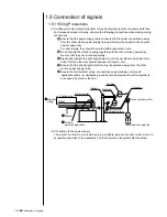
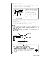
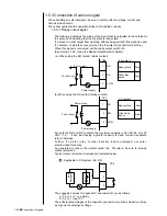
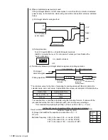
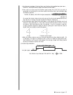
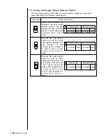
1.5.3-3 Warning signal output
The following describes the wiring of the signal that is outputted to the outside for the
purpose of indicating that the IJ printer is in the warning mode.
(a) When using the NO contact (make contact)
(b) When using the NC contact (break contact)
For both the NO and NC contacts, the maximum capacities of the fault and
warning condition outputs are 30 VAC/0.5A, or 30 VDC/1 A. If any load having a
greater capacity is used, furnish a separate relay in between.
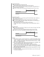
Further, if a motor, relay, or other inductive load is employed, a counter-
electromotive force may be generated to reduce the useful contact life.
Therefore, be sure to provide contact protection as suggested for the ready
output signal wiring.
7
8
9
NC
NO
COM
Power supply
Status indicator
lamp or the like
TB2
8-9 contact
Warning
state
Closed
Normal
state
Open
7
8
9
NC
NO
COM
Power supply
Status indicator
lamp or the like
TB2
7-9 contact
Warning
state
Closed
Normal
state
Open
Summary of Contents for PXR-D
Page 319: ...3S23L1307 3B PXR D E7 HEC ...


