


●
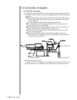
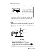
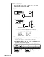
Connection of signals 1-25
¡
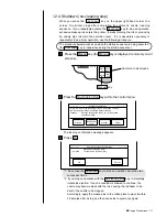
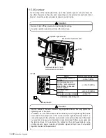
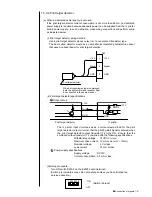
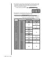
Layout of connectors for connection
Communication connector
External connection
terminal block 1
(TB1)
1#
17#
1#
9#
External connection
terminal block 2
(TB2)
SW1
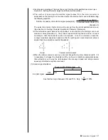
¡
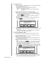
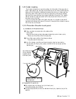
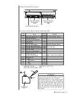
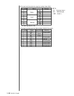
Connection to the external connection terminal block (TB1)
Pin
Name
Input/
Remarks
number output
1 Print target detector power supply
Output 12 VDC; maximum: 80 mA
2 Print target detector
Input
3 Print target detector ground
−
−
4 Printing stop
Input
5 Signal ground
−
−
6 Encoder power supply
Output 12 VDC; maximum: 80 mA
7 Encoder signal (totem pole)
Input
8 Encoder signal (open collector)
Input
9 Encoder ground
−
−
10 Deflection voltage ON/OFF
Input
11 Reverse direction printing signal
Input
12
Printing-in-progress/
Output Make a choice with an operating key.
printing-complete signal
13 Signal ground
−
−
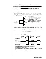
14
Run
Input
15
Reset (Clear)
Input
16
Stop
Input
17
Online
Output
Use either one.
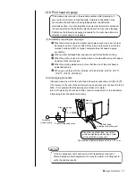
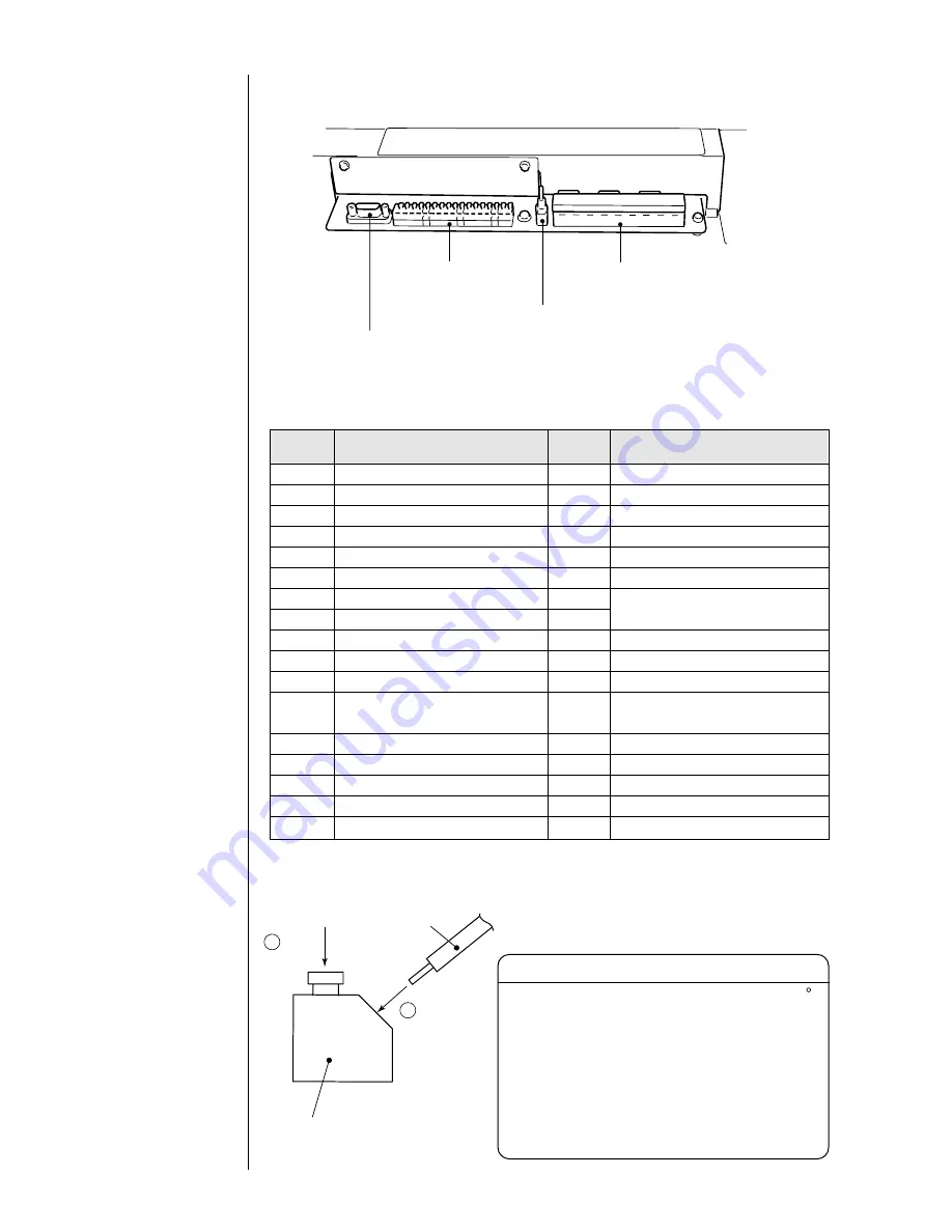
• Applicable cable size
: AWG26 to 14 (
φ
0.4 to 1.6)
• Wire covering to be stripped : 9mm
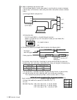
Terminal block
(TB1)
Wire
Push
1
2 Insert
UL Notice
Use UL Listed wire with 30V rating or more, 60 C
rating or more and VW-1 or FT-1 notation.
The length must be 3m or less. When length is
3m or more, use the wire of CL2 or CM grade of
the NEC standard. But the power supply line
from IJP to the exterior (No. 1 and No. 6 pin of
TB1) and connection lines with equipment of a
factory (conveyer etc.) can use only the wire of
CL2 grade.
Summary of Contents for PXR-D
Page 319: ...3S23L1307 3B PXR D E7 HEC ...


