


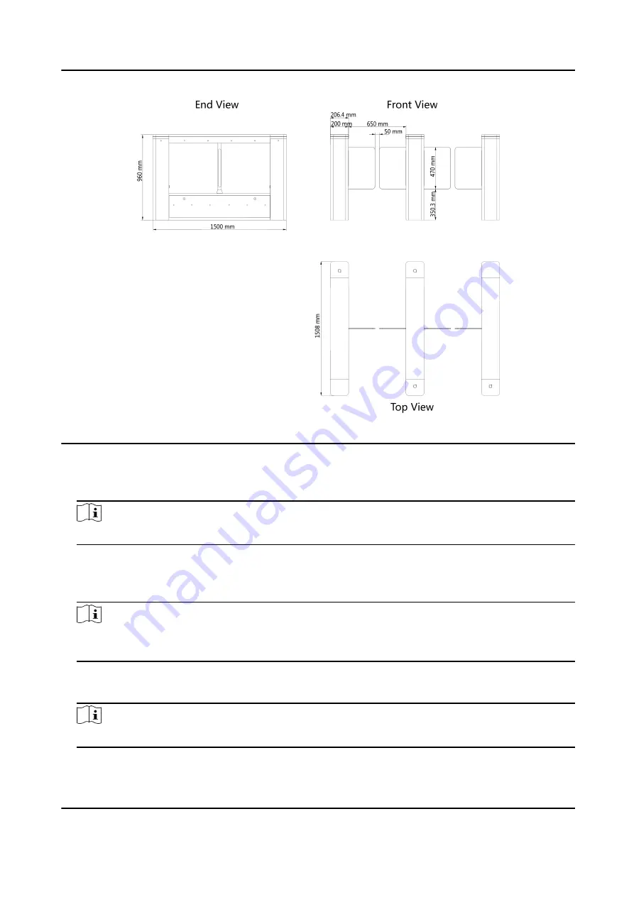
Figure 3-2 Dimension
1. Prepare for the installation tools, check the components, and prepare for the installation base.
2. Draw a central line on the installation surface of the left or right pedestal.
3. Draw other parallel lines for installing the other pedestals.
Note
The distance between the nearest two line is L+200 mm. L represents the lane width.
4. Drill holes on the ground according to the installation holes on the pedestals and insert the
expansion sleeves.
5. Bury interconnecting cables for pedestal communication.
Note
For detailed information about burying and wiring interconnecting cables, see Wire
6. According to the entrance and exit marks on the pedestals, move the pedestals to the
corresponded positions.
Note
Make sure the installation holes on the pedestals and the base are aligned with each other.
DS-K3B501S Series Swing Barrier User Manual
21
Summary of Contents for DS-K3B501S Series
Page 1: ...DS K3B501S Series Swing Barrier User Manual ...
Page 30: ...Entering Wiring Exiting Wiring DS K3B501S Series Swing Barrier User Manual 17 ...
Page 32: ...Figure 2 8 Fire Alarm Module Wiring DS K3B501S Series Swing Barrier User Manual 19 ...
Page 115: ...Figure F 2 Device Command DS K3B501S Series Swing Barrier User Manual 102 ...
Page 116: ...UD18744B ...


