x
IX.
TROUBLE SHOOTING
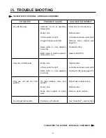
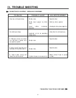
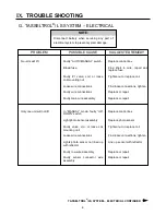
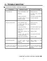
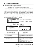
To gain further information on the status of the
Tasseltrol
®
/LS system before operation: while
sitting in the operator’s seat, turn the ignition key to
the “ON” position (do not start the engine); turn the
Tasseltrol
®
box to the “ON” position; turn the
“AUTO/MANUAL” switch to “MANUAL.”
Make sure there is nothing physically blocking
any upper or lower sensor’s path to its reflector.
TASSELTROL
®
/LS SYSTEM – ELECTRICAL CONTINUED
TASSELTROL
®
/LS SYSTEM – ELECTRICAL CONTINUED
TASSELTROL
®
DISPLAY TROUBLESHOOTING
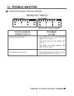
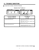
The display will show the status of the upper
and lower photo sensor on each lift assembly. If the
display shows a box (“ ”) in all upper and lower
areas, the unit is ready for operation. If the display
shows a corn stalk (“ ”) in one or more areas, refer
to pages XX-XX for further suggested remedies.
The LEFT-CENTER sensors are used as
examples.
Unit rises automatically.
AUTO
MODE
AUTO
P
UP
MANUAL
MODE
MANUAL
AUTO
UPPER PHOTO SENSOR DISPLAY
LOWER
PHOTO
SENSOR
TASSELTROL
®
DISPLAY
Lights at both photo sensors
No lights at either photo sensor
Photo sensors not in line with reflector (See
page XX)
Faulty connector cable (See page XXX, fig. 9.1,
item 2)
Faulty RED and/or BLACK wire in connector
cable (See page XXX, fig. 9.1, item 1)
PHOTO SENSOR
STATUS LIGHTS
POSSIBLE
CAUSE
Summary of Contents for 204
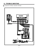
Page 133: ...x IX TROUBLE SHOOTING TASSELTROL LS SYSTEM ELECTRICAL CONTINUED FIG 9 1 1 2...
Page 134: ...x IX TROUBLE SHOOTING NOTES...
Page 140: ...138 NOTES...
Page 141: ...x...


