


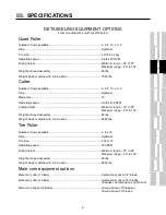
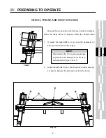


IV.
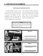
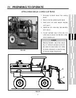
PREPARING TO OPERATE
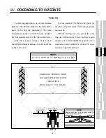
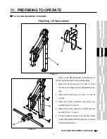
TREAD WIDTH CONTINUED
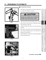
8. To adjust the tread out, place a suitable
prying tool under the center of the tire and
pry out at the same time that you push out at
the top of the leg (fig. 4.6). Carefully lower
the detasseler to the ground which, in turn
will allow the leg to slide outward. Repeat
the procedure until the desired tread is
obtained.
9. To adjust the tread in, raise the detasseler
until the tires on the side being adjusted are
just off the ground. Carefully lower the
detasseler which, in turn will allow the top of
the leg to slide in on the mainframe.
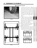
10. Retighten leg mounting bolts following the
torque specs and sequence on page XX.
11. Retighten the leg brace lock nut.
12. Repeat the above procedures to adjust and
set the opposite side legs. When finished, all
four legs should be the same distance from
x
FIG 4.6
FIG 4.7
B
B
B
B
A
A
DIM A (FIG 4.7) DIM B (FIG 4.7)
120”
=
25.5”
114”
=
22.5”
108”
=
19.5”
Tread Width
(Standard)
DIM A (FIG 4.7) DIM B (FIG 4.7)
90”
=
10.5”
84”
=
7.5”
78”
=
4.5”
Tread Width
(Narrow Tread Option)
Summary of Contents for 204
Page 133: ...x IX TROUBLE SHOOTING TASSELTROL LS SYSTEM ELECTRICAL CONTINUED FIG 9 1 1 2...
Page 134: ...x IX TROUBLE SHOOTING NOTES...
Page 140: ...138 NOTES...
Page 141: ...x...


