x
V.
OPERATING INFORMATION
CAB OPERATION CONTINUED
TASSELTROL PARAMETERS CONTINUED
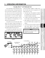
“ALL UP” and “ALL HOLD” Function
This function can be used to raise or lower all row
units at the same time. The switches to control this option
are located on the hydrostat control handle (5.33). All the
row units will move up when the red switch (5.33, item 1)
is activated and will lower when the green switch (5.33,
item 2) is activated.
The parameters for dwell on the up move can be set
to 0, 5, 10, 15, 20, or 25 seconds. The heads will move
up in this amount of time without having to hold the red
switch in. All heads will hold this position when the pa-
rameter is reached. To resume automatic depth control,
activate the green switch.
To program the “ALL UP” and “ALL HOLD” function:
1. Put the “AUTO/MANUAL” switch to “AUTO.”
2. Put the “ON/OFF” switch to “ON.”
3. Press the “UP” button under “PAR”.
4. Press the “UP” button under “MISC” (4 lift only. If 6
lift, skip to step 5.)
5. Press the “UP” button under “D” to set the dwell time.
6. After selecting one of the dwell time choices, press
any of the down switches.
7. To escape the parameter mode, press down a sec-
ond time to return to the original screen (this will save
the information on a 4 lift control; to save on a 6 lift
control, switch the AUTO/MANUAL toggle to MANU-
AL).
FIG 5.33
1
2
FIG 5.35
PRESS UP TO CHANGE
PARAMETERS
PRESS DOWN TO QUIT
PAR=s B1 R2 T3 L6 DØØ
FIG 5.34
1
LIFT
ON
OF
F
AUTO
MA
N.
DEPTH CONTROL
TASSELTROL / LS
SYSTEM 12
S. I. E. level 2.1
SELECT MANUAL
CABLE BOX sn: C98ØØ9
PAR=s B1 R2 T3 L8 DØØ
5
LIFT
6
LIFT
2
LIFT
3
LIFT
4
LIFT
Summary of Contents for 204
Page 133: ...x IX TROUBLE SHOOTING TASSELTROL LS SYSTEM ELECTRICAL CONTINUED FIG 9 1 1 2...
Page 134: ...x IX TROUBLE SHOOTING NOTES...
Page 140: ...138 NOTES...
Page 141: ...x...


