


V.
OPERATING INFORMATION
HYDRAULIC SYSTEM CONTINUED
x
Detasseling Heads
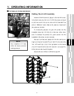
The hydraulic motors on the detasseling heads (fig. 5.23)
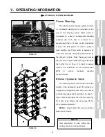
are turned on and off with a row of switches mounted on the
control panel to the right of the operator’s seat (fig. 5.22). To
open the solenoid on any of the motor control valves (fig. 5.21)
which activate the motors, flip the corresponding switch(es)
away from the operator’s seat. To shut any or all motors off, flip
the corresponding switch(es) toward the operator.
Each motor control valve contains a .182 inch orifice disc
that restricts hydraulic flow to the hydraulic motors so they don’t
overspeed and become damaged.
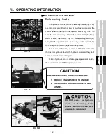
Activate hydraulic motors while engine speed is at an idle,
then increase engine RPM to operating speed.
FIG 5.22
DO NOT operate the hydraulic
motors on detasseling heads
without .182 inch orifices in place
under each solenoid coil.
FIG 5.21
FIG 5.23
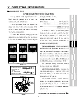
CAUTION
BEFORE ENGAGING HYDRAULIC MOTORS
1. REDUCE ENGINE SPEED TO AN IDLE
2. CLEAR AREA OF UNAUTHORIZED PER-
SONNEL
Summary of Contents for 204
Page 133: ...x IX TROUBLE SHOOTING TASSELTROL LS SYSTEM ELECTRICAL CONTINUED FIG 9 1 1 2...
Page 134: ...x IX TROUBLE SHOOTING NOTES...
Page 140: ...138 NOTES...
Page 141: ...x...


