NOTE:
Immediately reduce engine speed and shut off
ignition if any of the above “RED” indicator
lights illuminate. Determine cause and correct
before continuing operation.
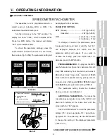
Speedometer/Tachometer -
(fig. 5.44, item 1)
Unit will display either engine RPM or speed of travel
depending on operator’s selection. See pages 60-61
for more information on the speedometer/tachometer.
Water Temperature -
(fig. 5.44, item 2) The
water temperature gauge monitors the engine cooling
system. A “RED” indicator light alerts the operator of
unsafe operating temperatures.
Engine Oil Pressure -
(fig. 5.44, item 3) The oil
pressure gauge monitors pressure of the engine
lubricating system. A “RED” indicator light alerts the
operator of low level operation.
x
V.
OPERATING INFORMATION
FIG 5.43
Fuel Gauge -
(fig. 5.44, item 4) The fuel gauge
measures the amount of fuel in either fuel tank,
depending on the tank selected with the fuel switch. A
“YELLOW” indicator light alerts operator of low level
operation.
Volt Meter -
(fig. 5.44, item 5) The volt meter
measures voltage from the alternator on the diesel
engine. A “RED” indicator light will alert the operator if
the system is operating either too low or too high.
Hour Meter -
(fig. 5.44, item 6) The hour meter
progressively records elapsed time of detasseler
operation. It is useful for determining service intervals.
Filter Minder (diesel only) –
(fig. 5.44, item 7)
See page 88 for information regarding the air filter
monitoring system.
GAUGE PANEL
FIG 5.44
1
2
3
5
4
6
7
Summary of Contents for 204
Page 133: ...x IX TROUBLE SHOOTING TASSELTROL LS SYSTEM ELECTRICAL CONTINUED FIG 9 1 1 2...
Page 134: ...x IX TROUBLE SHOOTING NOTES...
Page 140: ...138 NOTES...
Page 141: ...x...


