1-10
To do...
Use the command…
Remarks
Display information about the
received flush messages
display smart-link flush
Available in any view
Clear the statistics about flush
messages
reset smart-link statistics
Available in user view
Smart Link Configuration Examples
Single Smart Link Group Configuration Example
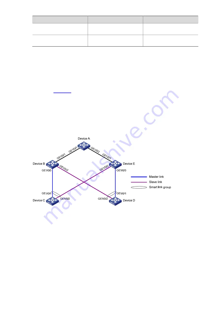
Network requirements
As shown in
z
Map VLANs 1 through 10, VLANs 11 through 20, and VLANs 21 through 30 to MSTI 0, MSTI 1, and
MSTI 2 respectively.
z
Traffic of VLANs 1 through 30 on Device C and Device D are dually uplinked to Device A.
z
Configure Smart Link on the devices for dual uplink backup, using VLAN 1 (the default) for flush
update.
Figure 1-2
Single smart link group configuration
Configuration procedure
1) Configuration on Device C
# Create VLANs 1 through 30, map VLANs 1 through 10, VLANs 11 through 20, and VLANs 21 through
30 to MSTI 0, MSTI 1, and MSTI 2 respectively, and activate the MST region configuration.
<DeviceC> system-view
[DeviceC] vlan 1 to 30
[DeviceC] stp region-configuration
[DeviceC-mst-region] instance 0 vlan 1 to 10
[DeviceC-mst-region] instance 1 vlan 11 to 20
[DeviceC-mst-region] instance 2 vlan 21 to 30
[DeviceC-mst-region] active region-configuration
[DeviceC-mst-region] quit
Summary of Contents for S5500-SI Series
Page 161: ...3 10 GigabitEthernet1 0 1 2 MANUAL...
Page 220: ...1 7 Clearing ARP entries from the ARP table may cause communication failures...
Page 331: ...1 7 1 1 ms 1 ms 1 ms 1 1 6 1 2 1 ms 1 ms 1 ms 1 1 4 1 3 1 ms 1 ms 1 ms 1 1 2 2 Trace complete...
Page 493: ...2 8...
Page 1111: ...1 10 Installing patches Installation completed and patches will continue to run after reboot...


