


iSXblue/SXBlue II GNSS Series Technical Reference Manual
33
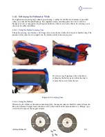
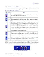
1.4.4 Definition of the LED Indicators
The iSXBlue/SXBLue II features diagnostic LEDs that provide a quick indication of the receiver’s status.
These LEDs are visible on the front panel display and provide the following information:
Table 1-5 LED Indicators Definitions
LED
Color
Function
Red
Power
– when the iSXBlue/SXBlue II GNSS is powered, this LED will illuminate. When battery is low, the Power
indicator will start blinking 20 minutes prior to auto shut-down.
Green
GPS Lock
– once the iSXBlue/SXBlue III GNSS achieves a solid GPS lock and computing a valid position, this
LED will remain illuminated. If this LED continues to blink, it could be an indication of a receiver hardware
failure.
Orange
DGPS Position
– this LED will illuminate when the receiver has achieved a differential position and the
pseudorange residuals are below that set with the $JLIMIT command and the computed solution is a 3D fix. The
default value is a pseudorange residual of better than 10.0 meters. If the residual value is worse than the current
threshold, the orange DGPS LED will blink indicating that differential mode has been attained but that the residual
has not yet met the threshold. The same happens when the PDOP exceeds the 10.5 factory default threshold and
switches to 2D mode (this is set with $JALT,sometimes,10.5).
For DGPS operation, the LED will blink to an amount of time equivalent to the $JAGE value (default is 3600
seconds) if the source of differential correction (ex. SBAS) is lost. The Coast technology will maintain submeter
accuracy for 30-40 minutes depending on ionospheric conditions.
For RTK operation under the MFA application, it will remain solid for 1 minute after the loss of RTK signal and
blink for an extra 2 minutes indicating a float solution; after a total of 3 minutes the receiver will switch to the next
best available differential correction source (ex. SBAS if available).
Yellow
Differential Lock
– this indicator will illuminate continuously when the iSXblue/SXBlue III GNSS has achieved a
solid SBAS or OmniSTAR lock (depending on model) with better than a 150 bit error rate (BER) or when it is
successfully receiving externally input RTCM/RTK corrections. For example, if the SBAS BER is higher than 150
but the receiver is still locked, this LED will blink, showing that lock is marginal.
Blue
Bluetooth
– this LED will illuminate when there is a Bluetooth connection between the iSXBlue/SXBlue II GNSS
and a Bluetooth compatible device and blinking, depending when there is no Bluetooth connection.
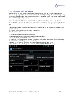
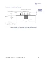
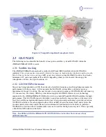
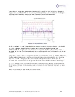
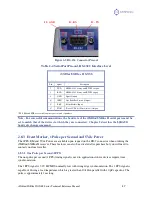
Note: When the iSXBlue/SXBlue II GNSS acquires a GPS lock, the green GPS lock LED will illuminate. Similarly, the yellow differential LED
(DIFF) will illuminate when differential corrections are being received successfully. The orange DGPS LED will illuminate when the receiver
has acquired a GPS lock, differential lock, and has applied corrections within the position solution. The following image displays the front panel
layout of the iSXBlue/SXBlue II receiver, including the location and labelling of each LED. For more information on LED operation and
troubleshooting, refer to Chapter 7.
Figure 1-16 iSXBlue/SXBlue II GNSS Front Panel


