GE
D
IRECTION
FQ091019, R
EVISION
2
V
IVID Q
N S
ERVICE
M
ANUAL
8-38
Section 8-3 - Internal Component Replacement Procedures
8-3-2-5
TR32 and RFI Boards Installation Procedure
NOTE:
This procedure applies to replacement of one or more of the defective boards (TR32A and/or,
TR32B and/or RFI).
NOTE:
When performing the following installation procedure steps, it may be helpful to review the
appropriate movie clips previously referenced in the
TR32 and RFI Boards Removal Procedure
.
1) Prepare
each
of the two TR32 Boards, as follows:
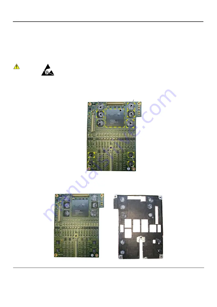
a.) Apply a small quantity of heat sink paste (
Dow Corning
®
340 Heat Sink Compound
, or similar)
to each of the eleven areas shown in
(marked with arrows).
b.) Attach the TR32 Board to its respective heat sink pad by placing the heat sink on the
TR32 Board (the obverse side of the heat sink is shown in
CAUTION
WHEN INSTALLING BOARDS, ESD MAY CAUSE DAMAGE TO A BOARD. ALWAYS
HAVE THE ESD HAND STRIP CONNECTED TO THE MACHINE CHASSIS AND TO
YOUR HAND.
Figure 8-44 TR32 Board Showing Areas for Application of Heat Sink Paste
Figure 8-45 TR32 Board Shown with Respective Heat Sink Pad


