


GE H
EALTHCARE
D
IRECTION
FC091194, R
EVISION
11
V
IVID
7 S
ERVICE
M
ANUAL
5 - 134
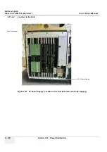
Section 5-11 - Power Distribution
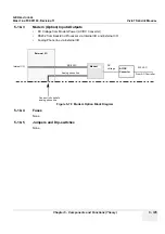
5-11-3-3
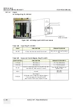
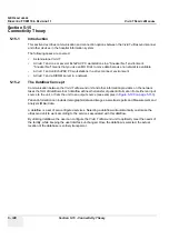
Inputs
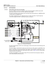
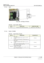
AC Voltage. Plug P1, 230 VAC
Figure 5-88 AC Voltage input to DC Power module
Table 5-86 Input, Plug P1, 230 VAC
INPUT
DESCRIPTION
CONNECTION FROM:
230 VAC
AC Input via a three pin male (IEC) mains inlet
Cable from the AC Power Distribution
Box
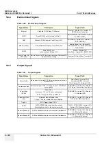
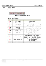
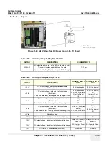
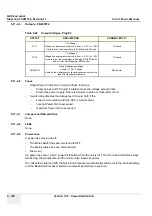
Table 5-87 Sense and Control Signals, Plug P3 and P4
INPUT/OUTPUT
DESCRIPTION
CONNECTION FROM/TO:
+ 3.3 Sense
Remote sense
+3.3 V from Motherboard
- 3.3 Sense
Remote sense
-3.3 V from Motherboard
PS_ON*
Active low control signal used to turn the DC Power ON.
Controls the AC Power output to TX Power.
From: ON/OFF (Standby) key on
Operator Panel
SYNC.
Not used
FEP1:
FEC
FEP2:
RFI
PWR_OK
Control signal.
Is high when the DC voltages are within specification.
Is low when power is on its way ON or OFF.
Used for control of AC Power output to TX Power.
P1
P2
Cable # 31-3
FROM AC POWER
Summary of Contents for Vivid 7
Page 1: ...GE Healthcare Operating Documentation Vivid 7 Service Manual Part Number FC091194 Revision 11...
Page 2: ......
Page 9: ...GE HEALTHCARE DIRECTION FC091194 REVISION 11 VIVID 7 SERVICE MANUAL vii JA ZH CN KO...
Page 38: ...GE HEALTHCARE DIRECTION FC091194 REVISION 11 VIVID 7 SERVICE MANUAL xxxvi...
Page 856: ...GE HEALTHCARE DIRECTION FC091194 REVISION 11 VIVID 7 SERVICE MANUAL Index 8...
Page 857: ......


