D
IRECTION
5771498-100, R
EVISION
5
V
ENUE
™ S
ERVICE
M
ANUAL
Chapter 5 - Venue™Components and Function (Theory)
5-3
P R E L I M I N A R Y
The Venue™ ultrasound scanner has a software beam-forming system.
Signal flow from the Probe Connector Panel, to the Front End (FE) Electronics, and to the Back End
Unit, are finally displayed on the cockpit (monitor).
5-2-1-1
System Configuration and Software
System configuration is stored on a hard disk drive inside the Back End Unit.
At power up, all necessary software is loaded from the hard disk.
5-2-1-2
Electronics
The Venue™ system internal electronics are divided into three:
•
•
•
- see page 5 - 26
Venue™ system internal electronics comprise an eTower that contains both the Front End Unit and the
Back End Unit. The Interconnecting signals between the two sections are routed internally via PCIe
cable. All the interconnections to the cockpit (monitor) and peripherals (data signals) are via the Back
End. All power signals are via the Main Power Board (MPB).
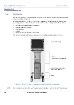
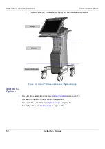
The design of the Venue™ ultrasound scanner comprises three main sections (illustrated in
):
•
Cockpit (monitor) - comprises user interface section
•
eTower - includes scanner electronic cards and assemblies
Summary of Contents for Venue R1
Page 477: ......


