Chapter 8 - Replacement Procedures
8-53
D
IRECTION
5771498-100, R
EVISION
6
V
ENUE
™ S
ERVICE
M
ANUAL
P R E L I M I N A R Y
8-4-9-5
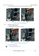
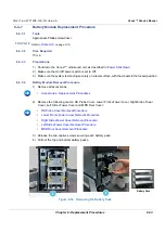
BEP PCB Installation Procedure
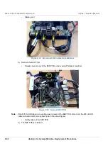
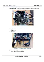
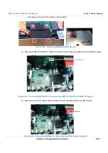
1.) Reconnect the BEP PCB using four screws in the PCB corners using Phillips screwdriver
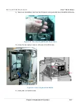
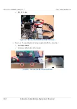
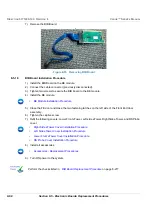
2.) Reconnect the following cables at the back of the BE:
•
Two USB connectors
•
Network cable
•
Display port
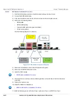
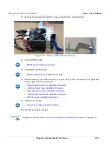
3.) Reconnect the following cable connectors:
•
SATA DATA BE TO SSD A (red cable)
Figure 8-41 Reconnect BEP PCB
Figure 8-42 Reconnect BE Cables from BE Back
Summary of Contents for Venue R1
Page 477: ......


