Chapter 8 - Replacement Procedures
8-131
D
IRECTION
5771498-100, R
EVISION
6
V
ENUE
™ S
ERVICE
M
ANUAL
P R E L I M I N A R Y
•
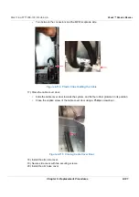
Three in the front end
•
One between the connectors and the MPB receptacle side.
12.)Close the cable cover door:
•
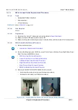
Slide the cable cover door towards the system, and fix the rubber grommet in its position
•
Close the captive screw of the cable cover door using a Phillips screwdriver.
13.)Install the arm side cover.
14.)Secure side cover with two securing screws.
15.)Install the arm base cover.
16.)Refit the following covers: Left Side eTower, Riser Thermal, Right Side eTower, Lower Front
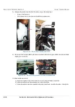
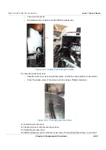
Figure 8-132 Plastic Clips Holding the Cable
Figure 8-133 Closing Cable Cover Door
Summary of Contents for Venue R1
Page 477: ......


