Chapter 8 - Replacement Procedures
8-65
D
IRECTION
5771498-100, R
EVISION
6
V
ENUE
™ S
ERVICE
M
ANUAL
P R E L I M I N A R Y
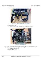
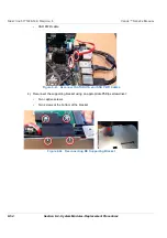
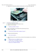
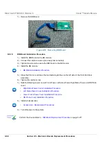
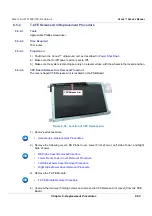
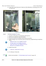
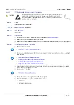
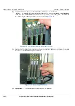
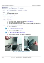
6.) Remove the PCIe plastic cable guide and attach it to the new T-PSB module.
8-4-12-5
T-PSB Module Installation Procedure
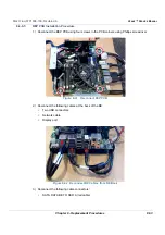
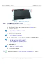
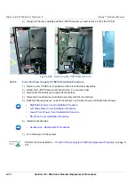
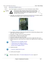
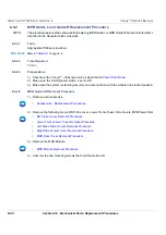
1.) Fit the T-PSB module and fasten with four screws.
2.) Install the T-CFE module.
3.) Install the T-FEPS module.
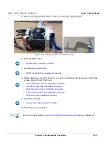
4.) Install the full Front End assembly:
5.) Refit the following covers: Lower Front eTower, Left side eTower, Right Side eTower, and RS Probe
Cover:
:
6.) Install all accessories.
7.) Turn ON power to the system.
•
Plastic Cable Guide for CFE Removal Procedure
•
T-CFE Module Installation Procedure
•
Front End Power Supply (T-FEPS) Installation Procedure
•
•
Right Side eTower Cover Installation Procedure
•
Left Side eTower Cover Installation Procedure
•
Lower Front eTower Cover Installation Procedure
•
RS Probe Cover Installation Procedure
•
Accessories - Replacement Procedures
Summary of Contents for Venue R1
Page 477: ......


