background image

CHAP

. 7

GE Healthcare

Senographe 2000 D Acquisition System

REV 1

OM 5179217–1–100

67

5.

BROWSER DISPLAY

5-1

Lists

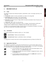
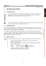
The Browser contains lists showing the patients, examinations, series, and images presently on the
image disk:

D

Patients list

: patients for whom examinations are stored on the image disk,

D

Examinations list

: examination for the selected patient 

Note: examinations are sometimes referred to as studies.

D

Series list

: the different series of images within the selected examination; Raw, Processed, and

Screen Save images.

D

Images list:

 images within the selected series.

The number of items (patients, examinations, series, or images) currently selected, and the total
number of items contained in the list, is displayed at the lower right corner of each list.

In addition to raw and processed images acquired locally by the Acquisition Workstation, the browser
lists may also include SCPT (Secondary Capture) images.

5-2

List format

The Browser displays lists of patients, exams, etc., in two formats:

Two-list format

;  Patients and examinations.

Four-list format

: Patients, examinations, Series, and Images.

To change from one format to the other, click the appropriate small icon just above the Patient list.

5-3

Application Controls

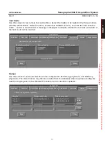
The Application control buttons to the right of the Browser lists are used to review images stored on
the workstation database, to start Quality Assurance Procedures (QAP), to input patient demographics
from the HIS/RIS, or to send a message to the local GE Service Center.

D

To review images stored on the workstation: select the desired images on the
Browser, then click on the 

(Review Exam)

 button.

D

To link with the HIS/RIS and access the Worklist  management function: click on
the 

(Worklist)

 button.

D

To start Quality Assurance Procedures: click on the 

(QAP)

 button; select the

required procedure from the list presented.

À

À

FOR 

TRAINING 

PURPOSES 

ONLY! 

NOTE: 

Once 

downloaded, 

this 

document 

is 

UNCONTROLLED, 

and 

therefore 

may 

not 

be 

the 

latest 

revision. 

Always 

confirm 

revision 

status 

against 

validated 

source 

(ie 

CDL).

Summary of Contents for Senographe 2000 D

Page 1: ...100 Revision 1 Do not duplicate CopyrightE 2006 by General Electric Company inc All rights reserved FOR TRAINING PURPOSES ONLY NOTE Once downloaded this document is UNCONTROLLED and therefore may not be the latest revision Always confirm revision status against a validated source ie CDL ...

Page 2: ...to prevent unauthorized or unqualified persons from operating this equipment or exposing themselves or others to its radiation Before operation persons qualified and authorized to operate this equipment should be familiar with the Recommendations of the International Commission on Radiological Protection contained in Annals Number 60 of the ICRP and with applicable national standards and should ha...

Page 3: ...f the Generator cabinet USA HHS United States Federal law restricts this device to use by or on the order of a physician General Electric Medical Systems is ISO 9001 and EN 46001 certified The original document was written in English All components of the Senographe 2000 D system Generator Cabinet Gantry Acquisition WorkStation Cart are designed to be suitable for use within the patient environmen...

Page 4: ...using other than recommended interconnect cables or by unauthorized changes or modifications to this equipment Unauthorized changes or modifications could void the users authority to operate the equipment All interconnect cables to peripheral devices must be shielded and properly grounded Use of cables not properly shielded and grounded may result in the equipment causing radio frequency interfere...

Page 5: ...s examples dry and wet cell batteries transformer oil etc Please consult your local General Electric Medical Systems representative before discarding these products Packing materials The materials used to pack our equipment are recyclable They must be collected and processed in accordance with the regulations in force for the country where the machines or accessories are unpacked FOR TRAINING PURP...

Page 6: ...isition System REV 1 OM 5179217 1 100 4 Blank page FOR TRAINING PURPOSES ONLY NOTE Once downloaded this document is UNCONTROLLED and therefore may not be the latest revision Always confirm revision status against a validated source ie CDL ...

Page 7: ...3 CONTRAINDICATIONS 20 4 TRAINING PROGRAM 20 5 HOW TO USE THE MANUAL 20 6 QUALITY CONTROL 21 7 CONVENTIONS FOR THIS MANUAL 21 7 1 Typographical 21 7 2 Definitions 21 8 SYSTEM COMPONENTS 22 8 1 Overview 22 8 2 Senographe 2000 D X ray System 22 8 3 Digital Detector and Image Receptor 23 8 4 Acquisition Workstation Cart 24 8 4 1 Overview 24 8 4 2 Three Section Table 25 8 4 3 Light Box 25 8 4 4 Writin...

Page 8: ...NTROL CONSOLE 43 4 CENTRAL SECTION OF CONTROL CONSOLE KEYBOARD 48 5 RIGHT HAND SECTION OF CONTROL CONSOLE 50 6 VIEW NAME SELECTION 52 6 1 View Names 52 6 2 Automatic View Name Selection 53 6 2 1 The automatic view selection process 53 6 2 2 Angles used in automatic view selection default values 53 6 3 Manual View Name Selection Standing or Sitting Patients 54 6 4 View Names for Recumbent Patients ...

Page 9: ... SHUTDOWN 66 4 LOCK SCREEN 66 5 BROWSER DISPLAY 67 5 1 Lists 67 5 2 List format 67 5 3 Application Controls 67 5 4 Network Panel 68 5 5 Status display 68 6 BROWSER MANAGEMENT 69 6 1 Selecting Images 69 6 2 Selecting Images 69 6 3 Status of Series 69 6 4 Sorting Lists 70 6 5 Deleting Images 70 6 6 Interchange Media 70 7 NETWORK TRANSFER 71 7 1 Network options 71 7 2 Transfer 71 8 TOOLS MENU UTILITI...

Page 10: ... 4 Image Acquisition New Examination 88 2 5 Image Review 89 3 BAR CODE SCANNER OPTION 90 3 1 Optional bar code scanner 90 3 1 1 How to read a bar code symbol 91 3 1 2 Set default configuration 91 3 1 3 How to enter an AWS text field 92 3 1 4 What If 92 CHAPTER 9 VIEWER 95 1 OVERVIEW 95 1 1 Viewing Area 96 1 2 Mosaic Image Browser 96 1 3 Image Selection 96 2 VIEW CONTROL 97 2 1 Zoom 97 2 2 2D Local...

Page 11: ...Composer area 109 5 4 Page navigation area 109 CHAPTER 10 IMAGE ACQUISITION PROCEDURE 111 1 OVERVIEW 111 2 PREPARATION 111 2 1 Worklist 111 2 2 Preparing the Equipment 111 3 CONFIGURATION 112 3 1 Standard exposures 112 3 2 Magnification 112 3 3 Examination of Chest Wall 112 4 AOP MODE 113 4 1 Use of Markers in AOP Mode 114 4 2 Mammary implants 114 5 MANUAL MODE 115 6 POSITIONING THE PATIENT 117 7 ...

Page 12: ...3 Restoring Images from Recordable CD 134 2 3 1 Procedure 134 2 3 2 Notes 135 2 3 3 Errors 135 2 4 Ejecting a Disk from the CD R Drive 136 CHAPTER 13 MAINTENANCE 137 1 CLEANING AND DISINFECTION 137 1 1 Monitor cleaning instructions 137 1 2 General Information about disinfection 137 1 3 Cleaning Instructions 138 1 4 Low Level or Intermediate Level Disinfection 138 1 5 High Level Disinfection 139 1 ...

Page 13: ...uency 166 1 1 7 Generator Power excluding tube 166 1 2 Maximum Tolerance of Displayed Constants 166 1 3 Workstation Storage 166 1 4 Digital Detector FOV 166 2 RADIATION AND FILTER INFORMATION 167 2 1 Radiation Reference Axis 167 2 2 Technical Leakage Factor 167 2 3 Filters and Anode Tracks 167 2 4 Attenuation Equivalence 168 3 AMBIENT CONDITIONS 168 3 1 Operational Ambient Conditions 168 3 2 Trans...

Page 14: ...sition System REV 1 OM 5179217 1 100 12 Blank page FOR TRAINING PURPOSES ONLY NOTE Once downloaded this document is UNCONTROLLED and therefore may not be the latest revision Always confirm revision status against a validated source ie CDL ...

Page 15: ...f the Senographe 2000 D in its most complete configuration If any of the options described in this manual are not included in your system skip the corresponding chapter or sections See your General Electric Medical Systems representative for the options available with the Senographe 2000 D system FOR TRAINING PURPOSES ONLY NOTE Once downloaded this document is UNCONTROLLED and therefore may not be...

Page 16: ...sition System REV 1 OM 5179217 1 100 14 Blank page FOR TRAINING PURPOSES ONLY NOTE Once downloaded this document is UNCONTROLLED and therefore may not be the latest revision Always confirm revision status against a validated source ie CDL ...

Page 17: ...diately if you believe that the equipment is not operating correctly 2 POTENTIAL ADVERSE EFFECTS D The following is a list of potential adverse effects that apply to mammography and are also applicable to digital mammography using the Senographe 2000 D system Excessive breast compression Excessive X ray exposure Electric shock Infection Skin irritation abrasions or puncture wounds 3 EMERGENCY SWIT...

Page 18: ...ecommendation is not followed D No application programs of any sort may be loaded onto the system computer without prior approval from GEMS GEMS cannot guarantee the integrity of the system if this recommendation is not followed D Only accessories and components supplied by or specifically recommended by GEMS may be used with the system GEMS cannot guarantee the integrity of the system if this rec...

Page 19: ...ly to allow correct processing of images to be completed before shutdown in the event of a power failure Certain conditions may cause a loss in the ability of the system to acquire high quality images or a risk that images might not be correctly saved for example if the UPS batteries are not sufficiently charged to ensure correct shutdown For these conditions a warning message is displayed on the ...

Page 20: ...ator of adequate thickness D Use the internal dose measurement facility D Protect the digital detector by means of a 3 mm steel plate for the duration of the measurements 9 DAMAGE TO THE DIGITAL DETECTOR The digital detector contains thallium doped cesium iodide a substance which requires special precautions for handling and recycling If the protective casing of the digital detector sustains damag...

Page 21: ...y The AWS is used for image acquisition processing and display The AWS can also be used for database management and can send images to archive review or filming D The Acquisition Workstation displays acquired images in the room allowing immediate evaluation of breast positioning and possible motion blur or adjustment of brightness and contrast Archiving Networking and Filming are all possible from...

Page 22: ...be the organization of the manual The Regulatory Requirements at the beginning of this manual pages 1 and 2 and the chapter on Safety Recommendations chapter 1 are extremely important describing safety and regulatory issues that you must thoroughly understand before attempting to use the Senographe 2000 D system The remainder of this introductory chapter contains a general description of system fe...

Page 23: ...thin parentheses View D On screen tools appear in bold face within braces Scroll Bar D On screen prompts and messages appear in italics Login D User typed in responses appear in bold face italics Senographe 2000 D D Keyboard hardkeys and mouse buttons are underlined Enter or left 7 2 Definitions The various safety and cautionary notes throughout this manual are defined as follows A HAZARD EXISTS T...

Page 24: ...aphe 2000 D Cart includes the AWS monitor keyboard and mouse computer electronics accessory storage and UPS Uninterruptable Power Supply 3 Accessories standard and optional The following sections describe each of these components 8 2 Senographe 2000 D X ray System The Senographe 2000 D is equipped with a dual track X ray tube molybdenum rhodium and a digital detector Mammographic examinations can ...

Page 25: ...ilt into the Image Receptor shown below It is a flat panel of amorphous silicon on which cesium iodide is deposited to maximize detection of X Rays and transmission of light photons The high definition digital images produced are sent to the Acquisition Workstation for visualization and processing The upper surface of the Image Receptor is a removable grid Bucky when the grid is not required it is...

Page 26: ...ase management and to send images to archive review or filming Refer to Chapter 5 Acquisition Workstation for a detailed description of the workstation functions The workstation is installed in the AWS Cart shown above Inside the cart are housed the workstation electronics AWS computer IDC image detection controller an accessory storage unit the Uninterruptible Power Supply UPS and the optional CD...

Page 27: ...on then pull it slightly upwards until the lock springs back into place The three section table is not designed to hold items in excess of 20 kg weight 8 4 3 Light Box You can use the light box for viewing comparison mammograms THE LIGHT BOX ON THE AWS CART MUST NOT BE USED FOR FINAL INTERPRETATION OF EXAMINATIONS THE AMBIENT LIGHT CONDITIONS IN THE EXAMINATION ROOM AND THE RESULTING LIGHT LEVEL O...

Page 28: ... 90 degrees either way for access from the side Ask your Field Engineer 8 4 6 Uninterruptible Power Supply UPS UPS front panel To assure system safety in the case of disturbances in the mains supply the Senographe 2000 D system incorporates an Uninterruptible Power Supply UPS housed in the lower part of the Senographe 2000 D cart During power fluctuations or brief interruptions the UPS assures a c...

Page 29: ...d to a high resolution DICOM MG compatible laser camera for film printing ONLY IMAGES PRODUCED BY GE RECOMMENDED LASER CAMERAS CAN BE USED FOR FINAL INTERPRETATION OF EXAMINATIONS FOR COMPATIBLE PRINTERS SEE THE LATEST PRODUCT DATA SHEETS FOR THIS SYSTEM WHICH YOU BE OBTAINED FROM YOUR LOCAL GE SALES REPRESENTATIVE D Networking The Senographe 2000 D is DICOM compliant allowing it to be connected i...

Page 30: ...cquisition System REV 1 OM 5179217 1 100 28 Blank page FOR TRAINING PURPOSES ONLY NOTE Once downloaded this document is UNCONTROLLED and therefore may not be the latest revision Always confirm revision status against a validated source ie CDL ...

Page 31: ...mages in all other cases D Standard or magnification examinations can be performed with either track Focal spot sizes are 0 3 for contact exams and 0 15 for magnification exams AOP Mode D The AOP Automatic Optimization of Parameters Mode controls radiation For a given priority dose reduction subject contrast or compromise of dose and contrast the AOP Mode provides automatic selection of the optimu...

Page 32: ...sole Generator Cabinet Protective screen Digital Detector Note Mandatory marking labels such as CE marking UL Listing labels and FDA labels are located on the bottom left hand side of the Generator Cabinet FOR TRAINING PURPOSES ONLY NOTE Once downloaded this document is UNCONTROLLED and therefore may not be the latest revision Always confirm revision status against a validated source ie CDL ...

Page 33: ...loor using the fixed base plate Readout Connecting cables to generator Emergency Stop push buttons one on each side Compression Decompression pedals the four pedal option also raises and lowers the Image Receptor Tube arm Support Receptor arm Support FOR TRAINING PURPOSES ONLY NOTE Once downloaded this document is UNCONTROLLED and therefore may not be the latest revision Always confirm revision st...

Page 34: ...t Note Do not attempt to use the handle at the rear of the arm to disengage and rotate the tube arm support separately The system will not allow exposures to be made with this arm disengaged D Rotation Shaft This couples the Positioning Arm to the Telescopic Column Silk screened markings indicate the angles of rotation D Telescopic Column This consists of two cylinders a fixed cylinder and a teles...

Page 35: ...r button once to select the last format used and to illuminate the centering light Press the button again as often as required to toggle between the three formats Large format 19 x 23 cm Medium format 13 x18 cm Reduced format 9 x 9 cm D Centering Light To illuminate the field coverage for 30 seconds press the button located at the rear of the collimator D Face protection This is mounted on the fro...

Page 36: ...foot pedals placed on the floor Maximum compression force speed of compression and decompression height are programmed by the system SET UP functions Manual adjustments to compression force can be made using the knobs located on each side of the compression paddle arm Turn the top of the knob towards the patient to increase compression away from the patioent to decrease compression To change a com...

Page 37: ...ever located on the left of the platform and pull the platform forward as shown on the label on top left side of platform When the magnification platform is inserted the small focal spot is automatically selected and the FOV is reduced to 9 x 9 Magnification factors are defined in the middle of a 4 cm thick breast i e 2 cm above the magnification platform The useable magnification factors correspo...

Page 38: ...rs towards you to release the Bucky or breast holder then pull it out Insertion Insert the Bucky or optional breast holder in the rails then push it in until you hear a click D Up Down Control Buttons are located at the top and bottom of each handrail Use these buttons to adjust the height of the Image Receptor by raising or lowering the Receptor Support Arm A protecting rim prevents patient acces...

Page 39: ...or environment D The cabinet is mounted on wheels for easy installation it is not recommended that it be moved in normal operation D Do not obstruct the ventilation slots D The push buttons visible on the cabinet supply power to the Cart and to the UPS They are normally used only for Service operations FOR TRAINING PURPOSES ONLY NOTE Once downloaded this document is UNCONTROLLED and therefore may ...

Page 40: ...ies Optional accessories available for the Senographe 2000 D Gantry include D Optical localizer consisting of cross hair and biopsy paddle for two dimensional biopsy D Examination chair D Accessories storage unit D Remote handswitch D Breast Holder D Bar code scanner Only Senographe 2000 D recommended accessories should be used with this equipment Failure to heed this warning may cause unexpected ...

Page 41: ...e messages D Controls power up down for all components of the Senographe 2000 D system Control Console 2001 in forward production from February 2002 Control Console CDRH GE Medical Systems kV mAs The Control Console can be placed on a suitable flat surface or installed on the protective lead screen Connecting cable to generator FOR TRAINING PURPOSES ONLY NOTE Once downloaded this document is UNCON...

Page 42: ...e Handswitch for Prep and Exposure For information on using the Control Console refer to Section 3 Note The symbol located on the control panel means that you must read the appropriate chapter in the operator manual before taking any action FOR TRAINING PURPOSES ONLY NOTE Once downloaded this document is UNCONTROLLED and therefore may not be the latest revision Always confirm revision status again...

Page 43: ...VERVIEW Control Console 2001 in forward production from February 2002 Control Console CDRH kV mAs Alternative symbol FOR TRAINING PURPOSES ONLY NOTE Once downloaded this document is UNCONTROLLED and therefore may not be the latest revision Always confirm revision status against a validated source ie CDL ...

Page 44: ...ocal Spot selection 16 Exposure indicator lamp 6 Focal Track selection 17 Exposure Disable indicator lamp 7 Filter selection 18 Centering Light ON button 8 Left Breast Selection 19 Exposure Interrupt indicator button and reset 9 Right Breast Selection 20 Prep 10 Special Views selection 21 Exposure button 11 kV and mAs readout 22 Compression release Button FOR TRAINING PURPOSES ONLY NOTE Once downl...

Page 45: ...F CONTROL CONSOLE Control Console 2001 in forward production from February 2002 Control Console CDRH Alternative symbol FOR TRAINING PURPOSES ONLY NOTE Once downloaded this document is UNCONTROLLED and therefore may not be the latest revision Always confirm revision status against a validated source ie CDL ...

Page 46: ...other system components the indicator lamp lights and the system startup procedure begins The Control Console displays the last configuration used Gantry power off switch STOP or Press the key to power off the Gantry only the indicator lamp lights Note For more information on startup and shutdown procedures refer to Chapter 6 FOR TRAINING PURPOSES ONLY NOTE Once downloaded this document is UNCONTR...

Page 47: ...ATIENT FRANC ENGL DEUTS ESPAN ITALI PORTU UNAVAILABLE VIEW MEDICAL LANGUAGE Password SPEED FORCE DECOMP BEEP FILM HEIGHT UNAVAILABLE Seno 2000 D WITH BEEP YES NO COMPRESSION SPEED FAST SLOW MAX COMPRESS FORCE daN xx daN END OF EXPOSURE DECOMP DECOMPRESSION HEIGHT yy cm VALID VALID VALID MEDICAL SET UP APPLICATION MODE YES NO FOR TRAINING PURPOSES ONLY NOTE Once downloaded this document is UNCONTRO...

Page 48: ...utomatic and pressing the key has no effect Filter selection Press the key to switch between the two filters molybdenum Mo and rhodium Rh D In Manual mode press the key to select the filter The readout indicates the filter selected Note Certain filter anode track pairs are inhibited according to the selected kV value The system automatically selects an authorized filter and displays the selection ...

Page 49: ...ew selection for standing or sitting patients When a special view is used which does not correspond to the automatic view selection press the Special Views Selection key as often as required until the desired view name is displayed Refer to Section 6 for details D Recumbent patients The automatic and special view selection procedure applies only to standing or sitting patients View names for recum...

Page 50: ...f the Control Console Keyboard is used to select and display the kV and mAs values Control Console 2001 in forward production from February 2002 Control Console CDRH FOR TRAINING PURPOSES ONLY NOTE Once downloaded this document is UNCONTROLLED and therefore may not be the latest revision Always confirm revision status against a validated source ie CDL ...

Page 51: ...me parameter selections may change these limits e g the X ray Console can display as high as 600 mAs whereas the exposure is automatically limited to 500 mAs There is no mechanical stop you can continue to turn the knob past the minimum or maximum value but the displayed value no longer changes D In AOP mode turning the knob has no effect AOP and Manual Mode selection Press the key to step through...

Page 52: ...d initiate an exposure control the centering light and for decompression and system reset Control Console 2001 in forward production from February 2002 Control Console CDRH FOR TRAINING PURPOSES ONLY NOTE Once downloaded this document is UNCONTROLLED and therefore may not be the latest revision Always confirm revision status against a validated source ie CDL ...

Page 53: ...ncelled preparation stops one second after release Exposure button Press and hold this button while the Prep key is lit to make an exposure To stop exposure immediately release the key A buzzer sounds at the end of exposure Note In AOP mode and following preparation anode rotation exposure is made in two stages D An absorption measurement exposure of about 4 ms which allows selection of the optimu...

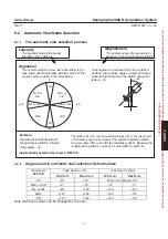
Page 54: ...Lateral Oblique MLO Inferior lateral side of breast against receptor MedioLateral 90_ ML Lateral side of breast against receptor LateroMedial 90_ LM Medial side of breast against receptor LateroMedial Oblique LMO Superior medal side of breast against receptor CranioCaudal from below FB Superior side of breast against receptor Superolateral to Inferiormedial Oblique SIO Inferior medial side of brea...

Page 55: ...lected laterality is R so the inferior side of the breast is against the receptor The system therefore selects the view name SIO and adds the laterality prefix R Because the magnification platform is present it also adds the prefix M Automatically selected view name R M SIO Example Operator selected laterality R Magnification platform Present Tube angle 45_ 180_ 0_ 90_ 90_ 6 2 2 Angles used in aut...

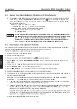
Page 56: ...section 3 once 4 Press VIEW to select the RECUMBENT PATIENT menu overriding the automatically selected view name 5 Press the or key as often as required until the correct view name is displayed 6 Press VALID to select and save the displayed name 7 Press SET UP twice to return to the main menu and acquire the patient image D Repeat these steps for each view acquired on the recumbent patient D The t...

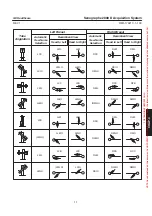
Page 57: ...LO LML LLM RFB RLM RML RLMO RSIO RMLO RLM RCC RFB RSIO RMLO RLMO Tube Angulation Head to Left Automatic View Name Selection Left Breast Head to Right Recumbent View Head to Left Automatic View Name Selection Right Breast Head to Right Recumbent View FOR TRAINING PURPOSES ONLY NOTE Once downloaded this document is UNCONTROLLED and therefore may not be the latest revision Always confirm revision sta...

Page 58: ...cquisition System REV 1 OM 5179217 1 100 56 Blank page FOR TRAINING PURPOSES ONLY NOTE Once downloaded this document is UNCONTROLLED and therefore may not be the latest revision Always confirm revision status against a validated source ie CDL ...

Page 59: ...ased upon a graphical multi window mouse driven interface Images lists menus and control panels are displayed within graphical windows on the Workstation monitor Selections are made using buttons menus and control panels etc by pointing and clicking with the mouse Software programs other than those supplied by General Electric Medical Systems specifically for use with this system must NOT be loade...

Page 60: ...stalling software It is not able to read image files from systems equipped with the CD R CD Recording Interchange Media option The monitor should be used in a suitably dark environment when reviewing a digital image The optimum ambient light level is 50 lux THE AWS MONITOR MUST NOT BE USED FOR FINAL INTERPRETATION OF EXAMINATIONS IT IS SET UP FOR OPTIMUM VISUALIZATION WITH AN AMBIENT LIGHT LEVEL O...

Page 61: ...tion by releasing the button Specific drag and drop operations are described in more detail in the appropriate sections of this manual Important Clicking the mouse button pressing a button selecting a menu item etc in this manual always refer to using the left mouse button unless the middle or right mouse button is specifically mentioned 4 2 Keyboard The keyboard is used for entering text at on sc...

Page 62: ...is acknowledged by clicking on OK or Cancel Note If the system does not respond because two or more windows are open one on top of another it is possible to recover by pressing the Front key on the keyboard several times if needed to access hidden windows 6 ON SCREEN TOOLS 6 1 Cursor The cursor is the on screen tool which you maneuver across the screen using the mouse to display pull down menus ma...

Page 63: ...d by the scroll bar images items in a Browser list etc you can place the cursor on the vertical rectangular bar within the scroll bar Then press and hold the left mouse button and drag the cursor up or down to move backward or forward through the list The vertical bar within the scroll bar shows you where you are within the list compared to the list as a whole Release the mouse button when the des...

Page 64: ...cquisition System REV 1 OM 5179217 1 100 62 Blank page FOR TRAINING PURPOSES ONLY NOTE Once downloaded this document is UNCONTROLLED and therefore may not be the latest revision Always confirm revision status against a validated source ie CDL ...

Page 65: ...rocedure by attempting to enter commands at this time NEVER switch off at the UPS Uninterruptible Power Supply except in emergency risk of data loss 3 EMERGENCY SHUTDOWN D In an emergency to cut power to the Gantry Press one of the Emergency Stop push buttons there is one on each side of the Telescopic Column D In an emergency to cut power to all system components Switch off the main circuit break...

Page 66: ...cquisition System REV 1 OM 5179217 1 100 64 Blank page FOR TRAINING PURPOSES ONLY NOTE Once downloaded this document is UNCONTROLLED and therefore may not be the latest revision Always confirm revision status against a validated source ie CDL ...

Page 67: ...displayed when the Senographe 2000 D system is first switched on Note that the Tools menu function section 9 allows a number of Browser display options so the windows and icons displayed may differ from that shown here The Browser is used to D Shut down the Senographe 2000 D system D Link with the HIS RIS Hospital Radiology Information System D Access to the Worklist for setting up and starting pa...

Page 68: ...ile on the disk the disk will be unuseable and must be replaced before the operation is repeated 3 SYSTEM SHUTDOWN D To shut down the Senographe 2000 D system click on the Power off icon at the lower right of the Browser window Power is removed from the Senographe 2000 D Gantry and Generator the AWS system follows a shutdown procedure lasting about two minutes designed to ensure that no informatio...

Page 69: ... 5 2 List format The Browser displays lists of patients exams etc in two formats Two list format Patients and examinations Four list format Patients examinations Series and Images To change from one format to the other click the appropriate small icon just above the Patient list 5 3 Application Controls The Application control buttons to the right of the Browser lists are used to review images sto...

Page 70: ... in progress D Database query If present indicates that a query is in progress local hard disk access This icon may appear only very briefly Any error messages that may result from a database query are also displayed in this position D Filter indicator If present indicates that a filter is currently applied see section 9 Click on the indicator to display the current local filter window D Current d...

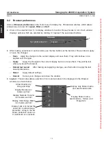
Page 71: ...ed all images of the series will be loaded and displayed To select a number of specific images hold down the Ctrl key on the keyboard and click on each of the desired images To select a range of images click on the first one in the range then hold down the Shift key and click the last one in the range 6 3 Status of Series The Status column in the Series list is used for single letter flags which i...

Page 72: ...ng the middle mouse button and drop it on the large Delete icon at the bottom right hand corner of the screen A message window pops up asking you to confirm the delete operation Click on OK to confirm or click on Cancel to cancel the operation If a Delete button is displayed in grey this indicates that the selected item is currently in use by an application Viewer or network transfer and therefore...

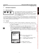
Page 73: ...tation or storage device remote host D Select the items you want to copy to the remote host in the Patient name Study ID series or imageslist D Either Drag the selected group using the middle mouse button and drop it over the icon representing the remote host in the Network Panel Or Use the Push function click on the Network Push button under the list to open the Network Push window if the button ...

Page 74: ...ally sent to the selected destination after exam closure D To archive exams on the mass archiver the archiver must be selected in the same way as a remote host select its icon as the drag and drop target or its address as the push destination During a network transfer D To monitor network transfer tasks click on the Network status display to open the Network queues window 65 3 1 2899 273 3 Done cl...

Page 75: ...ment Medical Application preferences Edit Patient Set patient anonymous Service desktop Restart Browser Shutdown Note Do not attempt to use items shown here with an asterisk They are intended for use only by your Field Service Engineer and are not described here uninformed use may lead to unpredictable results 8 1 Filter Management Click on Filter management in the Tools menu to Update Add or Remo...

Page 76: ...t do not save them They will be lost when you leave the browser Reload last saved After making and applying changes use this button to apply the last saved preferences Reset Apply default settings Cancel Cancel your changes and close the window D Layout This window allows selection of icons and windows to be displayed in the Browser window as shown below Display only Patient name and examinations ...

Page 77: ...te lists No Filter No Filter D Sort Use this window to specify a preferred order for displaying lists of patients and examinations series and images Sort patients by Yes No Split series Sort images by Number Sort series by Type Modality MG Sort exams by Date Last study date Note 1 Do not change the default choice of MG for Modality 2 Leave the selection of Split series as Yes Other selections are ...

Page 78: ...our Auto Push medAppPrefs Annotations Auto Delete Test Hosts Names Auto Push Auto Print Close Save Raw Proc None Both Raw Proc Both None Quality Check Auto Windowing Image process Auto Print Select Auto Print ON or OFF and the name of the desired DICOM printer Click the Printing properties button to set printing properties if required refer to Chapter 11 Printing Only the default print mode of Fit...

Page 79: ... Image process PrintingAnnotations Model 1 Model 2 Model 3 Auto Windowing Images are stored with four windowing levels High Standard Low and User Select which level is to be used as the default when an image is displayed If User is selected and no User level has been defined by a user saving the image with modified levels the Standard setting is used instead medAppPrefs Close Save Standard High Lo...

Page 80: ...essed images can be automatically removed from the AWS disk when they have been transferred Sent to another workstation or Committed by a mass archiver Note that when the function is turned on at least one of the profile buttons must be selected and if the used disk capacity reaches 95 the oldest exams are deleted by the system to make space for new ones ON OFF Auto Delete medAppPrefs Auto Delete ...

Page 81: ...Quality Check AutoWindowing Image process Names Use this screen to enter and store the names of Operators Performing physicians and Referring physicians The stored names may then be recalled from the database when required avoiding the need for retyping each time a Medical Procedure Card is created or updated medAppPrefs Define or modify names in database Operators Performingphysicians Referringph...

Page 82: ...ush Auto Print Quality Check AutoWindowing Image process Use this screen to enable or disable Premium View If Premium View is enabled it is applied to all eligible processed images generated by the Medical Application If Premium View is disabled this is the default setting when Premium View is first installed Thick ness Equalization is applied to all eligible processed images generated by the Medi...

Page 83: ...save is requested a confirmation message is displayed If the save is confirmed a message is displayed as a warning that a new entry will be made in the database and suggests that the old information should be manually removed Note that if the old records are not deleted repeated use of this facility can rapidly use up disk space 8 5 Set patient anonymous This option allows an anonymous set of imag...

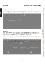
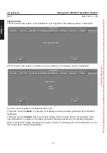
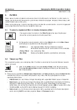
Page 84: ... is used only for the current Browser session and is not saved D Click on the Filter button and select Temp Filter in the drop down menu The Local temporary filter window is displayed in which you can specify the filter characteristics D Filters can be specified at Patient level Exam level and Series level By default Patient level is selected first but you can select these levels in any order clic...

Page 85: ...r is defined and saved registered separately Once defined and saved the name of the custom filter is added to the Filter menu It can then be used at any time using the Filter button and drop down menu D To create update or remove a custom filter select Filter management in the Tools menu The Filter selection window is displayed giving a list of registered filters and a list of options Update Modif...

Page 86: ...cquisition System REV 1 OM 5179217 1 100 84 Blank page FOR TRAINING PURPOSES ONLY NOTE Once downloaded this document is UNCONTROLLED and therefore may not be the latest revision Always confirm revision status against a validated source ie CDL ...

Page 87: ...t an exam select the required patient task in the list Selections can be made by clicking with the left mouse button or by entering appropriate text in one of the three Selection Criteria text boxes above the list Patient ID Patient Last Name or Accession Number When the correct patient task has been selected click the Start Exam button or double click on your selection to continue with Image Acqu...

Page 88: ... the window As soon as a character entry is made in one of the boxes Patient ID Patient Last Name Accession the window scrolls to show and select the first matching entry When an entry is made in one of the criteria boxes the other two are automatically cleared Click on the Refresh Worklist button to download the current worklist from the configured Dicom Worklist Provider If the Dicom worklist fe...

Page 89: ...the data stored on the barcodes can be scanned with the Barcode scanner option Scanning produces an MPC for each patient scanned saving time and reducing errors as compared with an exclusively manual data entry process PATIENT Name First Name Patient ID Birth Date START EXAM Medical Procedure Card CANCEL Year Month Day Sex Female EXAM DIGITAL SPOT Operator PerformingPhysician ReferringPhysician Ho...

Page 90: ...ust have unique identifiers name and ID mandatory first name optional D When the card entries are complete click on Save to add the patient to the Worklist for future use Start Exam to begin the exam or Cancel to exit If Start Exam is selected the Viewer opens with the Medical Procedure Card displayed Check the information displayed If it is not correct do not proceed select Cancel and confirm to ...

Page 91: ... display click on it in the list To add more images click on them in the list while holding down the Ctrl key on the keyboard t D Click the Review Exam button The same functions that are available after image acquisition image adjustment measurements annotations etc are also available in review mode with the exception of the 2D Localization function FOR TRAINING PURPOSES ONLY NOTE Once downloaded ...

Page 92: ...ymbols instantly The integrated decoder then transmits the data to the AWS workstation just as if data were entered from the AWS keyboard The supported bar codes symbologies are D Code 3 of 9 standard full ASCII D EAN 13 D Code 128 Handle light Figure 1 bar code scanner top view Handle Trigger Figure 2 bar code scanner bottom view LED CCD beam window Figure 3 bar code scanner side view FOR TRAININ...

Page 93: ... off D The handle light turns red 3 1 2 Set default configuration The scanner should already be configured If not programming the scanner is easy You just scan bar code menus In case you need to reset the bar code scanner to the supported AWS configuration follow the steps below 1 Reset the bar code scanner to the factory settings Wait until you hear 3 beeps 2 Start Settings You shall hear 2 beeps...

Page 94: ...de symbol as described in section 3 1 1 The decoded text is displayed in the text field just as if you typed it using the keyboard 3 1 4 What If Nothing happens when you follow the operating instructions D Check the system power D Check for loose cable connections The AWS workstation goes back to monitor ok prompt Resetting or disconnecting reconnecting the bar code scanner may make the workstatio...

Page 95: ...n D Be sure the bar code symbol is not defaced D The scan head must touch and cover every bar and space on the symbol as shown in Figure 5 You can tilt the scanner forward or backward Practice will quickly show you the ranges to work within Right Wrong Figure 5 Scan the entire symbol FOR TRAINING PURPOSES ONLY NOTE Once downloaded this document is UNCONTROLLED and therefore may not be the latest r...

Page 96: ...cquisition System REV 1 OM 5179217 1 100 94 Blank page FOR TRAINING PURPOSES ONLY NOTE Once downloaded this document is UNCONTROLLED and therefore may not be the latest revision Always confirm revision status against a validated source ie CDL ...

Page 97: ... Mosaic Image Browser 2 The Control Panel 3 Two selection buttons at the top of the panel allow one of two different Control Panels View Control and Annotation to be displayed according to the functions required Functions available from the two panels are described in section 2 Function panel 4 Provides access to the Medical Procedure Card image reprocessing image printing Middle mouse button func...

Page 98: ...up down arrow buttons to scroll through the full set To view images from the next or previous Series or Exam use the corresponding up down arrow buttons Ser or Exam Click on the desired image in the Mosaic Image Browser to display it in the viewing area A white dot on the reduced image in the Mosaic Image Browser identifies the currently displayed image A camera icon appears above the arrow button...

Page 99: ...d Brightness window width and window level sliders See description below D Image Control Use these controls to choose appropriate display parameters See description below 2 1 Zoom When the image is first displayed in the viewing area it is displayed with a Zoom factor called Fit to Screen The Zoom factor is calculated so that all of the image is displayed in the space available in the viewing area...

Page 100: ...n when the image is selected for review at a later stage On an image that has been saved on the database and is recalled in image review mode the 2D Localization cross hairs can no longer be modified or deleted 2 3 Contrast and Brightness sliders To use the sliders for precise adjustment of image contrast and brightness you can D Select the cursor of the slider and drag it left or right as require...

Page 101: ...he View Control panel shows the name of the windowing value currently applied To change it click the button and select the desired setting from the drop down menu 3 ANNOTATION To use the Annotation Level Control Panel click on the Annotation pencil icon to highlight it D Annotation Level Click on the appropriate icon to select the required annotation level See description below D Graphics Meas Cli...

Page 102: ... Hospital information 4 X Ray parameters 6 Processing information 7 Display parameters 5 Anatomical information 8 Measurements Cancel OK thickness ESE AGD Hospital Unit name name of performing physician D A small square button is displayed next to each group To select the annotation groups that you want displayed click on the corresponding button To deselect a group click on the square a second ti...

Page 103: ... handles around it four tick marks on the ellipse itself and a cross mark in the center D To change the size and shape of the ellipse press and drag on the handles D To rotate the ellipse around its center press and drag on any of the tick marks D To move the actual ellipse press anywhere on the ellipse except for the tick marks or on the center cross and drag the ellipse to its desired position T...

Page 104: ...rt text or use the Backspace key to delete text An arrow pointing to the area of interest can be attached to the annotation To do this select the small square next to Arrow When you have entered the text press the Apply button The window closes and the text annotation appears on the image To position the text annotation select it and drag it to the desired position If you chose to attach an Arrow ...

Page 105: ... Annotation Level buttons to set the amount of system annotation displayed See Annotation Level Level above 3 3 Geom Transformations The buttons in the Geom Transformations section of the panel allow you to flip or rotate the image to improve viewing comfort or for easier comparison with other images D Click the button for the desired action Flip image around horizontal axis The top of the image b...

Page 106: ...3 Reprocess D Click this button to apply the default processing algorithm to the currently selected image If the image has already been correctly processed or if it is an SCPT image the operation will have no effect 4 4 Close Exam Exit Viewer D Click this button to leave the Viewer If an exam has been reviewed with no changes the Viewer closes with no message If changes have been made to image WW ...

Page 107: ... value The new value is applied to both images raw and processed D This facility is available only in acquisition mode with the camera icon displayed in the Viewer Mosaic area At other times the button is grayed out and the wording on the button is QUALITY CHECK D If Auto Print is active it applies only to images with a Quality Check value of OK Images with a Quality Check value of NOT OK are not ...

Page 108: ...ouse button to move the image as required Note If the full content of the image is already displayed the Image Scroll function has no effect 4 7 3 Contrast Brightness control This function allows image contrast and brightness to be adjusted by moving the mouse D Click with the left mouse button on the Contrast Brightness button to select this function D To use the function move the mouse pointer o...

Page 109: ...To use the function either click the Scrapbook button on the Viewer Control Panel see section 4 2 or press the F3 keyboard function button The Scrapbook window is displayed D Scrapbook functions Use these buttons to select Scrapbook functions Print Print Menu Options Menu and Delete Menu See descriptions below D Page navigation area Use the arrows to display the next or previous pages See descript...

Page 110: ...u D Click this button to display a menu of print options Print page Prints the contents of the current Scrapbook page Print all pages Prints all pages of the Scrapbook Printing status Displays the Printing status panel see Chapter 11 Printer Configuration Displays the Print Manager panel Options Menu D Click the Options Menu button to display a two line pull down menu Select Options to display a c...

Page 111: ...e current page of the Scrapbook If there is no free slot a new empty page is created and displayed with the same layout format as the current page If the Scrapbook is not open the F4 key has no effect D To remove an individual image from the Scrapbbook click with the right mouse button on the thumbnail image in the composer area and answer Yes to the delete confirmation dialog which is displayed 5...

Page 112: ...quisition System REV 1 OM 5179217 1 100 110 Blank page FOR TRAINING PURPOSES ONLY NOTE Once downloaded this document is UNCONTROLLED and therefore may not be the latest revision Always confirm revision status against a validated source ie CDL ...

Page 113: ...Chapter 8 If the examination has not been scheduled and included in the Worklist a new entry can be made but image acquisition is not permitted until basic patient information has been recorded in the system After selection of the patient for whom you want to start acquiring images press the Start Exam button to continue with image acquisition The Viewer window Chapter 9 opens and exposures are pe...

Page 114: ...res are not permitted if the grid is present or the large focal spot is selected Check on the control panel display that the focal spot selection is shown as Small D Always make sure that the magnification platform is correctly locked in place before starting an exam D The object detector distance depends on the coefficient of magnification required D In manual mode increasing the kV setting by 1 ...

Page 115: ...est dose with respect for the user s imaging priority The operator chooses one of three options according to the priority required D CNT Contrast Gives priority to subject contrast D DOSE Dose Gives priority to dose reduction D STD Standard Selects a compromise between contrast and dose BREAST COMPRESSION OF AT LEAST 3 daN 30 NEWTONS OR 6 7 POUNDS IS ESSENTIAL WHEN USING THE AOP MODE The system au...

Page 116: ... as required Markers larger than 2 mm2 must not be present in the area used by the AOP algorithm Large markers will affect the calculation of tissue density which may lead to a degraded image Contact mode In contact mode exposures using AOP the area used is an area of 160 mm by 140 mm adjacent to the chest wall side and centered on the image receptor the shaded area in the diagram 4 2 Mammary impl...

Page 117: ...fer to Table 1 below Suggested Manual Techniques for suggested parameter selections according to breast type and thickness Table 2 Maximum and recommended kV ranges lists the available maximum and recommended kV ranges For thick 6 cm or dense breasts the Mo Rh and Rh Rh configurations may provide equivalent or better image quality with reduced patient dose As subject contrast depends on kV values ...

Page 118: ...80 29 80 Rh Rh 32 63 Rh Rh 32 140 Rh Rh 80 30 90 Rh Rh 32 140 Rh Rh 32 160 Rh Rh Without grid magnification examination 30 25 25 Mo Mo 27 28 Mo Mo 27 32 Mo Mo 30 40 26 40 Mo Mo 27 50 Mo Mo 28 56 Mo Mo 40 50 28 56 Mo Mo 28 80 Mo Rh 29 100 Mo Rh 50 60 29 71 Mo Mo 31 71 Mo Rh 30 63 Rh Rh 60 70 29 80 Mo Rh 30 63 Rh Rh 32 63 Rh Rh 70 80 29 71 Rh Rh 31 71 Rh Rh 32 125 Rh Rh 80 30 80 Rh Rh 31 160 Rh Rh 3...

Page 119: ...rom the waist up An appropriate cover should be provided during the waiting period It is important to relax the patient Any contraction of the pectoral muscles or muscles of the arm can cause an error in positioning Elevate the breast and center it on the image receptor over all its surface 1 Remove folds from the skin 2 Bring out the nipple and position it in profile when possible Do not sacrific...

Page 120: ... glandular dose Good compression is obtained when the compressed breast is taut to the touch Note As a safety measure the compression system is fitted with magnetic braking to avoid the paddle falling in the event of power loss If power loss occurs during an examination a force of around 5 daN will remain on the compression paddle Disengage the patient by lifting the paddle gently do not try to li...

Page 121: ...ews Selection key key in section 3 Chapter 4 to modify the view name b Recumbent patients Refer to section 6 4 in Chapter 4 press the control console SET UP key key in section 3 and use the VIEW RECUMBENT PATIENT menu to select the appropriate view name When the patient is positioned for a Cleavage view CV external markers must be used to assist in determining laterality when viewing the image Pla...

Page 122: ...e processed image replaces the raw image within a few seconds it is displayed with a standard contrast level but the user can choose a higher or lower contrast level using the View Control contrast setting see Chapter 9 Viewer After changing contrast select Auto to display the image with the new setting D As soon as an image has been transferred and displayed on the screen the system is ready for ...

Page 123: ...threshold level of gray selected to correspond to subcutaneous tissues is modified for more visibility The end result is clear visibility of the medical information in all regions of the breast When this algorithm is used the processing description applied is referred to as Proc 1 The Thickness Equalization algorithm is not applied to the following images Magnified Spot and Collimated views Images...

Page 124: ... the raw image on the screen The operator can select which of four levels of contrast should be applied High Low Standard or User defined selected in the Viewer Control Panel window For Premium View there is no predefined user value but User level can be set if the user saves the image with modified levels FOR TRAINING PURPOSES ONLY NOTE Once downloaded this document is UNCONTROLLED and therefore ...

Page 125: ...gnostic purposes and only images printed to 8 x 10 inch film have been validated for diagnostic purposes Do NOT use films formatted to print multiple images per sheet of film for diagnostic purposes The size of the printed mammogram depends on the type of workstation used to send the image to the printer and which printing method is used to print the film Use the following table for guidance Clini...

Page 126: ...hat have been declared for printing Click on a printer in the list to select it D Auto Print buttons click the On button to turn Auto Print on for the selected printer or the Off button to turn it off The selected button becomes dark gray D Save button click this button to confirm any changes made and close the window D Close button click this button to close the Medical Application preferences wi...

Page 127: ...on a printer in the list to select it D Print mode Can not be changed Fit to Film only D Number of Copies box enter the required number of copies in this box D Printing properties button click this button to open the Printing Properties window see below 3 3 D Print button click this button to print the displayed image on the currently selected printer D Queue button click this button to open the P...

Page 128: ...type Film size cannot be changed with the current Senographe 2000 D release software D Media type Blue film must be selected by default with Senographe 2000 D Other choices will incur printing errors D Destination Processor must be selected by default when using Senographe 2000 D Other choices will incur printing errors D Film orientation Portrait must be selected by default when using Senographe ...

Page 129: ...ting status window by clicking the Queue button It displays a list of jobs in the print Queue allowing the user to check that print jobs have been successfully sent to the printer note that a local printer problem can prevent a job from being printed even if it is successfully sent to the printer If any communication problems are observed with the printer or network the user is able to Refresh Pau...

Page 130: ...ns panel see Chapter 7 The illustrations below show the three models In each case the model is illustrated by a view with the chest wall to the right Model 1 Institution physician and patient data at top followed by view data Image and exposure data at bottom Top and bottom annotation areas are aligned to the border opposite the chest wall CHAP 11 FOR TRAINING PURPOSES ONLY NOTE Once downloaded th...

Page 131: ...llowed by exposure date and time Patient data at bottom left institution data at bottom right followed by exposure data The top annotation area is aligned to the border opposite the chest wall All bottom annotations are restricted to the image footer so as to avoid overlap with the image CHAP 11 FOR TRAINING PURPOSES ONLY NOTE Once downloaded this document is UNCONTROLLED and therefore may not be ...

Page 132: ...on System REV 1 OM 5179217 1 100 130 Blank page CHAP 11 FOR TRAINING PURPOSES ONLY NOTE Once downloaded this document is UNCONTROLLED and therefore may not be the latest revision Always confirm revision status against a validated source ie CDL ...

Page 133: ...t the handling instructions below 2 1 Handling CD R Media To avoid image loss never touch the recordable surface of a recordable CD CD R Handle the disk only by the outer edge Do not place it face down on a hard surface Fingerprints or scratches will make the disk unusable Before usage verify that CD R surface has no visible scratches If there are any scratches do NOT use the CD R D Store the disk...

Page 134: ...he CD R drive to be ready when light on CR R drive stops blinking D On the Browser select the patient or patients to be saved in the same manner as selecting images for review click on the required patient name in the browser list to select multiple patients hold down the CTRL key and click successively on each required patient name D Use the middle mouse button to drag the selected patient s to t...

Page 135: ...n select Query in the drop down menu If all the patients selected for the save operation are not displayed on the Media Browser an error has occurred while recording the CD and you will have to repeat the save operation D An error message appears next to the patient name if the associated information has not been saved If this occurs Make a list of the patients correctly saved and those with an er...

Page 136: ...r Sort by Number Sort by Refresh button Sort by button above each list Restore button under each list Quit button Tools menu button Patients list Status line series list 1 4 examinations 1 2 series 1 16 patients D In the Media Browser select the patient s and or exam s to be restored in the same manner as on the main Browser see Chapter 7 Browser D Sort the lists as required using the Sort by butt...

Page 137: ...played in the Main Browser after the images have been restored 2 3 3 Errors If a problem occurs an error message is displayed D The following message may be displayed during preparation for saving files and needs specific action Save selection exceeds CD capacity Save aborted Explanation You have selected more patient files than can be stored on a single CD Action Select fewer patients to be saved...

Page 138: ...omatically press the eject button If Detach is displayed in grey and no save or restore operation is in progress the archive device is already unlocked Press the eject button to open the drive If a fault occurs for example trying to start a restore operation with a blank disk in the drive the Detach operation is performed automatically and the disk is ejected NEVER press the Open Close button on t...

Page 139: ...roughly clean and disinfect equipment surfaces that contact the patient and all equipment surfaces likely to become soiled during use The level of disinfection required for a patient contact device depends on the type of contact that occurs D A CRITICAL device is one which routinely penetrates the skin or mucous membranes during use and therefore poses a high risk of infection if it is not sterile...

Page 140: ...es may be removed from the equipment and immersed if needed Equipment parts such as the Bucky Image Receptor that enclose electrical components must not be immersed but rather cleaned with a soft dampened cloth taking care not to allow liquids to enter the equipment Surfaces should be scrubbed as needed using a soft sponge gauze or cloth to remove all visible residue Scrubbing with a soft bristle ...

Page 141: ...ction VESPHENE IIse manufactured by Calgon Vestal Laboratories St Louis MO U S A EPA Reg No 1043 87 510 k K931573 According to the manufacturer when used according to the manufacturers instructions this product is effective against Acinetobacter calcoaceticus ATCC 19606 Candida albicans clinical isolate Candida parapslilosis clinical isolate Citrobacter freundii ATCC 8090 Enterobacter aerogenes AT...

Page 142: ...tions this product is effective against all of the above with the exception of Salmonella choleraesuis 1 6 2 High Level Disinfection CIDEX manufactured by Johnson Johnson Medical Inc Arlington TX U S A EPA Reg No 7078 1 EPA Est No 36126 PR 1 510 k K924434 CIDEX A CLEANING SOLUTION CONTAINS GLUTARALDEHYDE DIRECT CONTACT IS CORROSIVE TO EXPOSED TISSUE CAUSING EYE DAMAGE AND SKIN IRRITATION DAMAGE DO...

Page 143: ...ogs ÓÓÓÓÓÓÓ ÓÓÓÓÓÓÓ 6 ÓÓÓÓÓÓÓÓÓÓÓÓÓÓÓÓÓÓÓÓÓ ÓÓÓÓÓÓÓÓÓÓÓÓÓÓÓÓÓÓÓÓÓ Acquisition Backup ÓÓÓÓÓÓÓ ÓÓÓÓÓÓÓ 12 ÓÓÓÓÓÓÓÓÓÓÓÓÓÓÓÓÓÓÓÓÓÓÓÓÓÓÓ ÓÓÓÓÓÓÓÓÓÓÓÓÓÓÓÓÓÓÓÓÓÓÓÓÓÓÓ ÓÓÓÓÓÓÓÓÓÓÓÓÓÓÓÓÓÓÓÓÓÓÓÓÓÓÓ Inspection and functional checks ÓÓÓÓÓÓÓÓÓÓÓÓÓÓÓÓÓÓÓÓÓ ÓÓÓÓÓÓÓÓÓÓÓÓÓÓÓÓÓÓÓÓÓ Check Emergency Stop Buttons ÓÓÓÓÓÓÓ ÓÓÓÓÓÓÓ 12 ÓÓÓÓÓÓÓÓÓÓÓÓÓÓÓÓÓÓÓÓÓ ÓÓÓÓÓÓÓÓÓÓÓÓÓÓÓÓÓÓÓÓÓ Check Cable Grounding ÓÓÓÓÓÓÓ ÓÓÓÓÓÓÓ 24 ÓÓ...

Page 144: ...ÓÓÓÓÓÓÓÓÓÓÓÓÓÓÓÓÓÓ ÓÓÓÓÓÓÓÓÓÓÓÓÓÓÓÓÓÓÓÓÓÓ Check Breast Thickness Measurement ÓÓÓÓÓÓ ÓÓÓÓÓÓ 6 ÓÓÓÓÓÓÓÓÓÓÓÓÓÓÓÓÓÓÓÓÓÓ ÓÓÓÓÓÓÓÓÓÓÓÓÓÓÓÓÓÓÓÓÓÓ Check Grid Presence Sensor ÓÓÓÓÓÓ ÓÓÓÓÓÓ 12 ÓÓÓÓÓÓÓÓÓÓÓÓÓÓÓÓÓÓÓÓÓÓ ÓÓÓÓÓÓÓÓÓÓÓÓÓÓÓÓÓÓÓÓÓÓ Change Gantry CPU battery ÓÓÓÓÓÓ ÓÓÓÓÓÓ 36 ÓÓÓÓÓÓÓÓÓÓÓÓÓÓÓÓÓÓÓÓÓÓ ÓÓÓÓÓÓÓÓÓÓÓÓÓÓÓÓÓÓÓÓÓÓ ÓÓÓÓÓÓÓÓÓÓÓÓÓÓÓÓÓÓÓÓÓÓ Check light beam centering ÓÓÓÓÓÓ ÓÓÓÓÓÓ ÓÓÓÓÓÓ 24 ÓÓÓÓÓÓÓÓ...

Page 145: ...essage is mentionned GAN issued from Gantry GEN from generator AWS from Acquisition workstation Table 2 lists error messages displayed on the AWS screen Table 1 Error Messages displayed on the Gantry Msg No Source Message on Column Readout Message on Control Console Explanation Corrective Action E 01 GEN None Generator failure Problem reported in HV section of generator Switch OFF Gantry then swit...

Page 146: ...ry then switch ON If the problem continues note ALL messages and contact GEMS Field Service You can still work with molybdenum focal track E12 GEN None Checksum error gen Calibration parameters have been modified Switch OFF Gantry then switch ON If the problem continues note ALL messages and contact GEMS Field Service E13 GEN None Gen Arm communication fail Generator cannot communicate with arm Sw...

Page 147: ...on power OFF the whole system and wait for the end of the shutdown sequence 4 Restart the system 5 If the problem persists note ALL messages and inform GEMS Field Service E20 GEN None Check Main Distribution Rack Supply of AWS Cart and Detector environement circuits is not authorized 1 Switch OFF the Gantry 2 Switch ON 3 If the problem persists note ALL messages and inform GEMS Field Service E21 G...

Page 148: ...art the system 5 If the problem persists note ALL messages and inform GEMS Field Service E35 GEN None SYSTEM SHUTDOWN STARTED A power OFF of the whole system has been started The generator will power off the supply of Detector Gantry and Generator in fiew minutes Stop system usage and wait the end of the shutdown sequence E36 GEN None CART PWR FAILURE SYST SHUTDOWN The system shutdown has been pro...

Page 149: ...OFF Gantry then switch ON If the problem continues note ALL messages and contact GEMS Field Service E58 GAN Collim Fail Front Collimator Failure A problem has been reported in the Front collimator blade so correct format cannot be ensured Switch OFF Gantry then switch ON If the problem continues note ALL messages and contact GEMS Field Service E64 GAN Filter Fail Filter Positionning Failure A filt...

Page 150: ...isition again 4 If the problem continues note ALL messages and contact GEMS Field Service 5 Nevertheless you can continue to use the system with manual acquisition I07 GEN None Selected filter not allowed Al Filter selected by the operator not allowed The Senograph automatically selects the next correct filter 1 Press Filter selection to have the correct filter selected I12 GEN None Maximum mAs Ma...

Page 151: ...calibration is in progress Wait end of calibration If no calibration in progress power OFF ON the DMR I17 GEN None AWS SENO comm lost AWS system cannot communicate with Generator May be a service PC laptop is connected in place of AWS or may be the AWS cart is powered OFF for service need 1 Wait end of service operation if there is one else wait 1mn to allow the system to recorver itself 2 If the ...

Page 152: ...using molybdenum focal track I23 GEN None Console communication fail Generator Control Console connection is faulty Switch OFF Gantry then switch ON If problem continues note ALL messages and contact GEMS Field Service I24 GEN None Line power interruption Micro power cut occurred on line supply Switch OFF Gantry then switch ON If the problem continues note ALL messages and contact GEMS Field Servi...

Page 153: ...progress AWS set up in progress loading of Flat Field map after a new filter was selected No action required This message is displayed for two seconds after selection of a new filter I50 GAN Lock Jammed Lock Jammed LOCK PROBLEM In spite of command lock release does not operate Try again to release lock If the problem continues note ALL messages and contact GEMS Field Service I51 GAN Hot Lock Lock ...

Page 154: ...h ON If problem continues note ALL messages and contact GEMS Field Service I73 GAN Rotat Fail Rotation Brake Failure Rotation brake is not functioning correctly Switch OFF Gantry then switch ON If problem continues note ALL messages and contact GEMS Field Service I74 GAN Lock Failure Arm Lock Failure Arm lock is not functioning correctly Switch OFF Gantry then switch ON If problem continues note A...

Page 155: ...es by changing the parameter in the Setup Medical menu Otherwise no action is required this information is normally displayed I98 GAN Column Fault Column Up Impossible Elevator up movement is not possible 1 Check if any movement switches up down rotation were pressed during power ON If yes release the necessary switches and restart the Gantry system 2 Check if obstacle preventing up movement 3 Com...

Page 156: ...f the shutdown sequence 4 Restart the system 5 If the problem persists note ALL messages and inform GEMS Field Service S08 GEN None Required power is too high Power requested in Manual Mode is too high Reduce kV or mAs values S09 GEN None No compression detected Breast is not compressed Breast compression is mandatory S10 GEN None Generator cooling mn Generator requires xxxx minutes to cool Wait f...

Page 157: ...inished 2 If message persists 10mn after the AWS login power OFF the whole system and wait for the end of the shutdown sequence 5 Restart the system 6 If the problem persists again note ALL messages and inform GEMS Field Service S22 GEN None Waiting for IDC boot Communication with Image Detection Control sysetm is not yet established 1 Wait Image detection Control boot is finished 2 If message per...

Page 158: ...sure in progress has been aborted by the operator or the equipement but the system processed and display the image that has been generate 1 Look at the message displayed when the reset button is highlighted to know the real problem 2 Press reset and perform the action required by the last displayed message S38 GEN None Abort by HV arcing Wait Image Acq S39 GEN None Abort by IDC Wait Image Acquisit...

Page 159: ...mal value specified for best Image Quality Check image quality on current exam If the problem persists note ALL messages and inform GEMS Field Service S85 AWS None S85 Detector environment failure The environment of the detector is failed 1 Switch OFF the whole system and wait for the end of the shutdown sequence 2 Restart the system 3 If the problem persists note ALL messages and inform GEMS Fiel...

Page 160: ...e S90 AWS None S90 AWS not available close exam No more AWS ressources to continue examlem occurs in AWS 1 Close exam 2 Increase free space on image disk by deleting exams that have been archived 3 If the problem persists note ALL messages and inform GEMS Field Service S91 AWS None S91 Need user action on AWS Operator input is required on AWS Answer to AWS pop up S92 AWS None S92 AWS busy please w...

Page 161: ... if several application is running if yes close one S97 AWS None S97 AWS reset in progress wait The AWS is completing a reset operation No action required wait for completion of the reset S98 AWS None S98 Exp inhibited CAL IQ in progress The current application is CALtool or IQtool No exposure is requested by this application No action required S99 AWS None S99 OFFSET ACQUISITION IN PROGRESS The c...

Page 162: ...lease wait A system initialization process is in progress Wait until system initialization is complete AA 6 No Ups Power Backup A UPS error has been detected or communication with the UPS has been lost 1 Stop system usage and shut down the system 2 Check the mains power supply 3 Check on UPS panel that the batteries are charging Do not attempt to restart the system unless the batteries have been r...

Page 163: ...Please call service The UPS selftest has detected that the battery requires replacement Stop system usage and contact GEMS Field Service AA 14 UPS output overload Please call service An UPS overload condition has been detected Stop system usage and contact GEMS Field Service BB These messages relate to boot reset events BB 1 AWS IDC communication failure exam forbidden Communication between the AW...

Page 164: ...ges A GE Insite connection is in progress no new images should be acquired No action is required wait for completion of the connection BB 9 Restart browser must be performed to take into account the new configuration Medical Application Preferences setttings have been changed and Save has been requested The changes will not take effect until the Browser has been restarted Restart the Browser BB 10...

Page 165: ...e AWS memory It is still possible to perform film examinations 1 Perform system shutdown 2 Start up system 3 If the problem persists contact GEMS Field Service CC 8 Reallocation of disk space failed There is no space available on disk for acquiring more images Image disk is full or server has failed 1 Close exam 2 Increase free space on image disk by deleting exams that have been archived 3 Perfor...

Page 166: ...cquisition System REV 1 OM 5179217 1 100 164 Blank page FOR TRAINING PURPOSES ONLY NOTE Once downloaded this document is UNCONTROLLED and therefore may not be the latest revision Always confirm revision status against a validated source ie CDL ...

Page 167: ...urrent crest factor 1 7 at 200 V to 2 at 415 V 1 1 3 Input impedance The apparent resistance of the mains supply RL must be less than that which would cause a voltage drop of 6 at the maximum power load of 9 kVA For a nominal supply voltage of 380 V the line resistance RL 380 must be less than 1 Ω RL 380 1 Ω For other supply voltages calculate the equivalent permissable resistance value in ohms as...

Page 168: ...tube Connect a waveform analyzer Tektronix 7854 to the output of the divider the analyzer receives a signal proportional to the voltage applied to the tube The mAs values are given by mAs ŕT2 T1 i dt Where T1 is the time at which the high voltage reaches 75 of its maximum value and T is the time at which the high voltage returns to 75 of the maximum value Compression Force and Breast Thickness D C...

Page 169: ...AL SPOT Mo Rh Large 100 mA max 75 mA max Small 40 mA max 40 mA max The filters are installed on a disk driven by a stepping motor which moves from one filter to the other Two different filters are supplied D Molybdenum 0 03 mm D Rhodium 0 025 mm Note The Column electronics control the filters according to operator requirements in manual mode or to software requirements in AOP mode TARGET VOLTAGE k...

Page 170: ...spheric pressure 700 hPa min 1060 hPa max 3 2 Transport and Storage Ambient Conditions D Humidity 10 min 50 max 95 max no longer than two weeks D Temperature 10_C 50_F min 25_C 77_F max 10_C 14_F 50_C 122_F no longer than 1 day D Atmospheric pressure 500 hPa min 1060 hPa max 3 3 Ambient Light Level Senographe 2000 D monitors are adjusted for use in an optimum light level of 50 lux 4 TUBE INFORMATI...

Page 171: ...ÑÑÑÑ ÑÑÑÑ ÑÑÑÑ ÑÑÑÑ 490 ÑÑÑ ÑÑÑ ÑÑÑ ÑÑÑ 19 5 ÑÑÑÑÑ ÑÑÑÑÑ ÑÑÑÑÑ ÑÑÑÑÑ 2200 ÑÑÑÑÑ ÑÑÑÑÑ ÑÑÑÑÑ ÑÑÑÑÑ 86 5 ÑÑÑÑ ÑÑÑÑ ÑÑÑÑ ÑÑÑÑ 90 ÑÑÑ ÑÑÑ ÑÑÑ ÑÑÑ 198 ÑÑÑÑÑÑÑÑ ÑÑÑÑÑÑÑÑ ÑÑÑÑÑÑÑÑ Senographe 2000 D accessories ÑÑÑÑ ÑÑÑÑ ÑÑÑÑ 900 ÑÑÑÑ ÑÑÑÑ ÑÑÑÑ 35 5 ÑÑÑÑ ÑÑÑÑ ÑÑÑÑ 500 ÑÑÑ ÑÑÑ ÑÑÑ 20 ÑÑÑÑÑ ÑÑÑÑÑ ÑÑÑÑÑ 890 ÑÑÑÑÑ ÑÑÑÑÑ ÑÑÑÑÑ 35 ÑÑÑÑ ÑÑÑÑ ÑÑÑÑ 50 ÑÑÑ ÑÑÑ ÑÑÑ 110 ÑÑÑÑÑÑÑÑ ÑÑÑÑÑÑÑÑ AWS cart ÑÑÑÑ ÑÑÑÑ 1060ÑÑÑÑ Ñ...

Page 172: ...cquisition System REV 1 OM 5179217 1 100 170 Blank page FOR TRAINING PURPOSES ONLY NOTE Once downloaded this document is UNCONTROLLED and therefore may not be the latest revision Always confirm revision status against a validated source ie CDL ...

Page 173: ...remium View option Maintenance chapter modified to include revised monitor cleaning instructions and planned maintenance procedures Removed list of addresses of GE Medical Systems Service offices Updated cover pages This publication is contained in a multibook Master Folder It is a slave publication To maintain this publication it is mandatory to use the Master Folder 5161686 n 800 as the Interlea...

Page 174: ...ured by GE Medical System SCS BP 34 F78533 BUC CEDEX France www gehealthcare com Imagination at work FOR TRAINING PURPOSES ONLY NOTE Once downloaded this document is UNCONTROLLED and therefore may not be the latest revision Always confirm revision status against a validated source ie CDL ...

Reviews: