


3–18
489 GENERATOR MANAGEMENT RELAY – INSTRUCTION MANUAL
CHAPTER 3: INSTALLATION
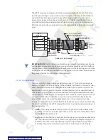
Voltage differences between remote ends of the communication link are not uncommon.
For this reason, surge protection devices are internally installed across all RS485 terminals.
Internally, an isolated power supply with an optocoupled data interface is used to prevent
noise coupling.
Note
To ensure that all devices in a daisy-chain are at the same potential, it is imperative that
the common terminals of each RS485 port are tied together and grounded only once, at
the master. Failure to do so may result in intermittent or failed communications.
The source computer/PLC/SCADA system should have similar transient protection devices
installed, either internally or externally, to ensure maximum reliability. Ground the shield at
one point only, as shown below, to avoid ground loops.
Correct polarity is also essential. All 489s must be wired with all ‘+’ terminals connected
together, and all ‘–’ terminals connected together. Each relay must be daisy-chained to the
next one. Avoid star or stub connected configurations. The last device at each end of the
daisy chain should be terminated with a 120
Ω
¼ W resistor in series with a 1 nF capacitor
across the ‘+’ and ‘–’ terminals. Observing these guidelines will result in a reliable
communication system that is immune to system transients.
FIGURE 3–18: RS485 Communications Wiring
3.2.13 Dielectric Strength
It may be required to test a complete motor starter for dielectric strength (“flash” or hi-pot”)
with the 489 installed. The 489 is rated for 1.9 kV AC for 1 second, or 1.6 kV AC for 1 minute
(per UL 508) isolation between relay contacts, CT inputs, VT inputs, trip coil supervision,
and the safety ground terminal G12. Some precautions are required to prevent damage to
the 489 during these tests.
Filter networks and transient protection clamps are used between control power, trip coil
supervision, and the filter ground terminal G11. This filtering is intended to filter out high
voltage transients, radio frequency interference (RFI), and electromagnetic interference
(EMI). The filter capacitors and transient suppressors could be damaged by application
continuous high voltage. Disconnect filter ground terminal G11 during testing of control


