


CHAPTER 7: TESTING
489 GENERATOR MANAGEMENT RELAY – INSTRUCTION MANUAL
7–7
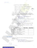
(EQ 7.3)
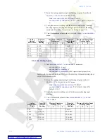
Therefore, the negative sequence current is 14% of FLA. The specification for negative-
sequence current accuracy is per output current inputs. Perform the steps below to verify
accuracy.
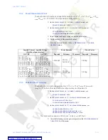
Z
In the
S2 SYSTEM SETUP
ZV
GEN. PARAMETERS
menu, set:
GENERATOR RATED MVA: “
1.04”
VOLTAGE PHASE-PHASE:
“600”
Note that setting
VOLTAGE PHASE-PHASE
to “600” is equivalent to setting FLA = 1000 A. This
is for testing purposes only!
Z
In the
S2 SYSTEM SETUP
Z
CURRENT SENSING
menu, set:
PHASE CT PRIMARY:
“
1000 A”
Z
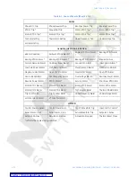
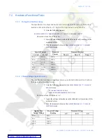
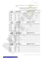
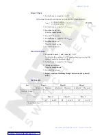
Inject the values shown in the table below and verify accuracy of the
measured values.
Z
View the measured values in the
A2 METERING DATA
Z
CURRENT
METERING
menu.
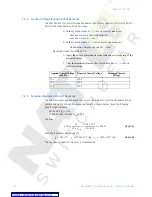
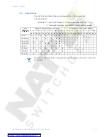
7.2.6
RTD Accuracy
The specification for RTD input accuracy is
±
2
°
for Platinum/Nickel and
±
5
°
for Copper.
Perform the steps below.
Z
In the
S8 RTD TEMPERATURE MENU
, set:
RTD TYPE
Z
STATOR RTD TYPE:
“100 Ohm Platinum” (select desired type)
RTD #1
Z
RTD #1 APPLICATION:
“Stator” (repeat for RTDs 2 to 12)
Injected Current
Expected Negative
Sequence Current
Measured Negative
Sequence Current
1 A Unit
5 A Unit
Ia = 0.78 A
∠
0
°
Ib = 1 A
∠
113
°
lag
Ic = 1 A
∠
247
°
lag
Ia = 3.9 A
∠
0
°
Ib = 5 A
∠
113
°
lag
Ic = 5 A
∠
247
°
lag
14% FLA
Ia = 1.56 A
∠
0
°
Ib = 2 A
∠
113
°
lag
Ic = 2 A
∠
247
°
lag
Ia = 7.8 A
∠
0
°
Ib = 10 A
∠
113
°
lag
Ic = 10 A
∠
247
°
lag
28% FLA
Ia = 0.39 A
∠
0
°
Ib = 0.5 A
∠
113
°
lag
Ic = 0.5 A
∠
247
°
lag
Ia = 1.95 A
∠
0
°
Ib = 2.5 A
∠
113
°
lag
Ic = 2.5 A
∠
247
°
lag
7% FLA
I
ns
1
3
---
I
a
a
2
I
b
aI
c
+
+
(
)
where
a
1 120
°
∠
0.5
–
j
0.866
+
=
=
=
1
3
---
780 0
°
∠
1 120
°
∠
(
)
2
1000
113
°
–
∠
(
)
1 120
°
∠
(
)
1000 113
°
∠
(
)
+
+
(
)
=
1
3
---
780 0
°
∠
1000 127
°
∠
1000 233
°
∠
+
+
(
)
=
1
3
---
780 601.8
–
j
798.6 601.8
–
j
798.6
–
+
(
)
=
141.2
–
=
%
I
ns
⇒
I
ns
FLA
---------
100
×
14%
=
=


