


CHAPTER A: APPENDIX
489 GENERATOR MANAGEMENT RELAY – INSTRUCTION MANUAL
A–5
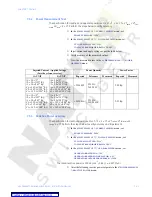
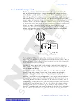
grounding impedance is inductive, the plane of operation will be the 270° plane, again,
with the polarity convention shown below. If the polarity convention is reversed on one
input, the user will need to change the plane of operation by 180°.
FIGURE A–4: Ground Directional Element Polarities and Plane of Operation
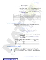
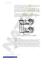
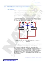
FIGURE A–5: Ground Directional Element Conceptual Arrangement
The operating principle of this element is quite simple: for internal ground faults the two
signals will be 180° out of phase and for external ground faults, the two signals will be in
phase. This simple principle allows the element to be set with a high sensitivity, not
normally possible with an overcurrent element.
The current pickup level of the element can be adjusted down to 0.05
×
CT primary,
allowing an operate level of 0.25 A primary if the 50:0.025 ground CT is used for the core
balance. The minimum level of
V
neutral
at which the element will operate is determined by
hardware limitations and is internally set at 2.0 V.
Because this element is directional, it does not need to be coordinated with downstream
protections and a short operating time can be used. Definite time delays are suitable for
this element.
808735A1.CDR
GENERATOR
I
o
CORE
BALANCE
CT
Plane of operation
for resistive
grounding impedance
180°
270°
0°
90°
Isolating
Transformer
489
Relay
V
o
F10
E10
H10
G10
I
o
I
o
I
o
±
±
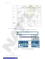
808734A1.CDR
GENERATOR
CORE
BALANCE
CT
BREAKER
Aux.
Contact
Grounding
Switch
To Relay
Grounding
Impedance
(Trans. &
Resistor)
Grounding
Switch
Aux. Cont.
G.S.
Status
Breaker
Status
Ground
O/C
Element
Isolating
Transformer
V
Input
neutral
Ground
Directional
Element
(or O/C)
489
Neutral
O/V
Element
Ground
Current
Input
Aux.
Breaker


