


CHAPTER 7: TESTING
489 GENERATOR MANAGEMENT RELAY – INSTRUCTION MANUAL
7–15
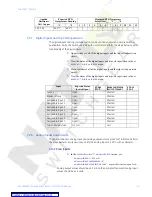
GENERATOR PHASE SEQUENCE:
“ABC”
Z
In the
S3 DIGITAL INPUTS
Z
BREAKER STATUS
menu, set:
BREAKER STATUS:
“Breaker Auxiliary a”
Z
In the
S6 VOLTAGE ELEMENTS
ZV
PHASE REVERSAL
menu, set:
PHASE REVERSAL TRIP:
“Unlatched”
ASSIGN TRIP RELAYS:
“1---”
Z
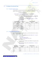
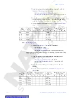
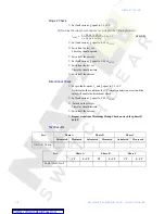
Apply voltages as per the table below. Verify the operation on voltage
phase reversal
7.3.5
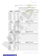
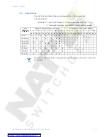
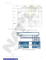
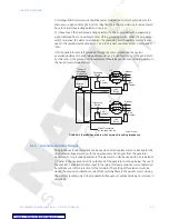
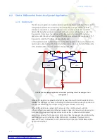
Injection Test Setup #2
Set up the 489 device as follows for the GE Multilin HGF Ground Accuracy Test, Neutral
Voltage (3rd Harmonic) Accuracy Test, and the Phase Differential Trip Test.
FIGURE 7–2: Secondary Injection Setup #2
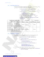
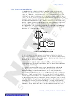
7.3.6
GE Multilin 50:0.025 Ground Accuracy
The specification for GE Multilin HGF 50:0.025 ground current input accuracy is
±
0.5% of
2
×
CT rated primary (25 A). Perform the steps below to verify accuracy.
Z
In the
S2 SYSTEM SETUP
Z
CURRENT SENSING
menu, set:
Applied Voltage
Expected Result
Observed Result
Va = 120 V
∠
0
°
Vb = 120 V
∠
120
°
lag
Vc = 120 V
∠
240
°
lag
No Trip
Va = 120 V
∠
0
°
Vb = 120 V
∠
240
°
lag
Vc = 120 V
∠
120
°
lag
Phase Reversal Trip
E10
V
NEUTRAL
1A
HGF
1A/5A
1A/5A
1A/5A
1A/5A
1A/5A
1A/5A
COM
COM
COM
COM
COM
PHASE a PHASE b PHASE c
PHASE A PHASE B PHASE C
COM
COM
COM
Va
Vb
Vcom
Vc
H9
G3
G6
H4
H7
H1
F10
A
B
C
N
A
B
C
N
V V V V
I
I
I
I
3 PHASE VARIABLE AC TEST SET
GROUND INPUTS
NEUTRAL END CT's
OUTPUT CT's
PHASE
VOLTAGE INPUTS
G10
H3
H6
G5
G8
H2
808817A1.CDR
G9
50:0.25
NC
NC
H10
G4
G7
G2
H5
H8
G1
AUTOMATIC CT
SHORTING
BAR
VC
VA
VB


