


CHAPTER 7: TESTING
489 GENERATOR MANAGEMENT RELAY – INSTRUCTION MANUAL
7–17
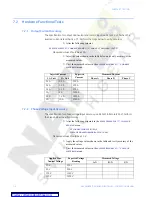
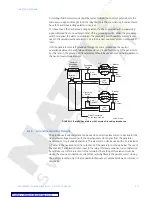
Minimum Pickup Check
Z
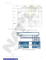
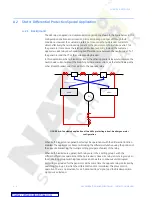
Connect the relay test set to inject Channel X current (
I
x
) into the G3
terminal and out of H3 terminal (Phase A). Increase
I
x
until the
differential element picks up.
Z
Record this value as pickup.
Z
Switch off the current.
The theoretical pickup can be computed as follows:
(EQ 7.5)
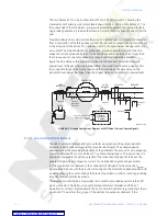
Single Infeed Fault
Z
Set the
I
x
prefault current equal to 0.
Z
Set the fault current equal to CT.
Z
Apply the fault.
Z
Switch off the current.
Z
Record the operating time.
Z
Set the
I
x
prefault current equal to 0.
Z
Set the fault current equal to 5
×
CT.
Z
Apply the fault.
Z
Switch off the current.
Z
Record the operating time.
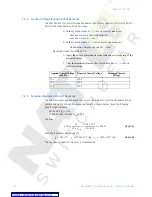
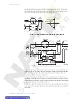
Slope 1 Check
Z
Connect the relay test set to inject Channel Y current (
I
Y
) into the G6
terminal and out of H6 terminal.
The angle between
I
x
and
I
Y
will be 180°.
Z
Set pre-fault current,
I
x
and
I
Y
equal to zero.
Z
Set fault current,
I
Y
equal to 1½ CT.
At this value the relay should operate according to the following formula:
(EQ 7.6)
Z
Set fault current,
I
x
equal to 0.95
×
I
XOP
1
.
Z
Apply the fault.
The relay should operate.
Z
Switch off the current.
Z
Set fault current,
I
x
equal to 1.05
×
I
XOP
1
.
Z
Apply the fault.
The relay should restrain.
Z
Switch off the current.
I
XPU
Pickup setting CT
×
=
I
XOP
1
2 Slope 1 setting
–
2 Slope 1 setting
+
----------------------------------------------
3 CT
×
2
---------------
×
=


