11-
10
LPS-D Line Protection System
GE Power Management
11.4 SETTING UP YOUR HOST MACHINE
11 ALPS-LINK USER GUIDE
11
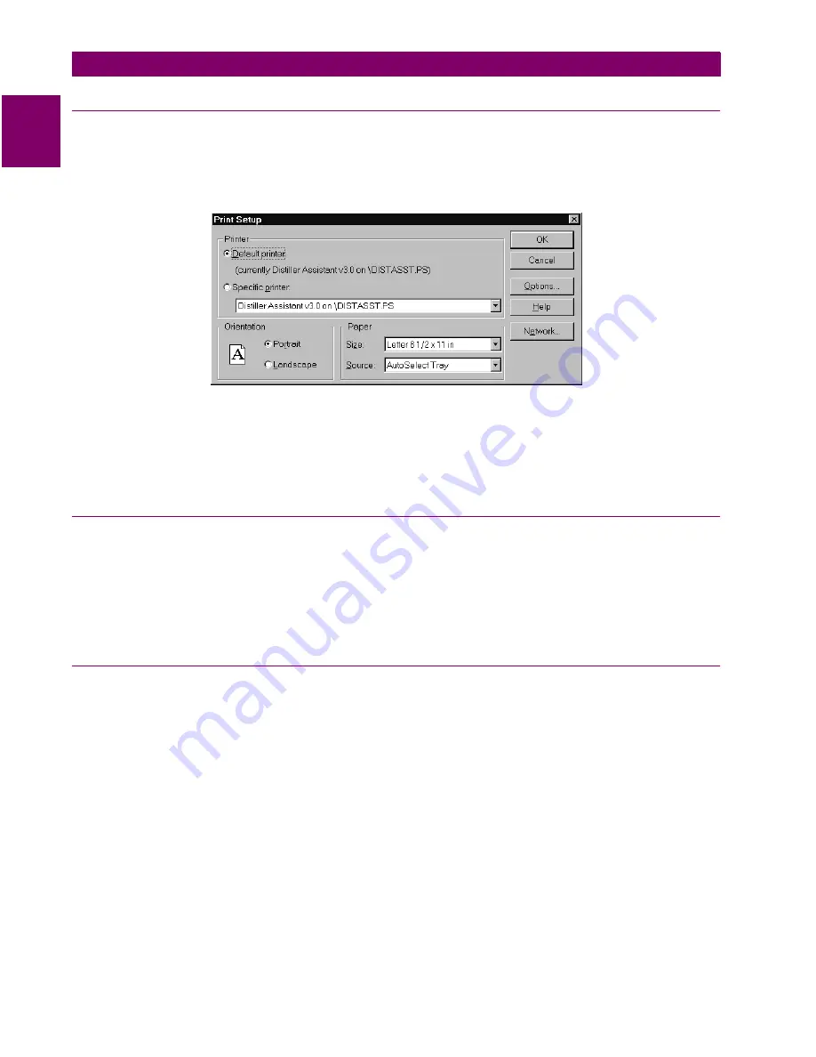
11.4.4 PRINTER SETUP
The hard copies for reports, logs and settings are made through the printer connected to the host machine.
The host machine need to be configured with the printer setup.
The Printer setup is performed from the SupportFunc menu. Choose the Host Setup item from the Support
Func pull down menu in the menu bar. From the pop-up menu choose the Printer item.
Figure 11–9: PRINTER SETUP DIALOG BOX
Select the printer you want to use. You can select the Default Printer by clicking that radio button or choose
the Specific Printer option by clicking on that radio button and select one of the current installed printers
shown in the box. Click on the Options button to get additional choices about printing, specific to the type of
printer you have selected.
11.4.5 DEVICE SETUP
More than one LPS-D device could be connected to the host machine on the physical link. But, at any given
time, ALPS-Link can communicate with a single device. It is possible that each of these devices are configured
with various communication parameters: for example, telephone number, baud rate, etc. ALPS-Link should be
setup with these details so that it can make proper connections with the devices. The Device Setup facilitates
updating ALPS-Link with this information. If you need to add a device or modify the existing communication
parameters of a device, Device Setup provides you the necessary interface.
11.4.6 ADDING A DEVICE
You can introduce a new device to ALPS-Link system or modify the setup of an existing device using the
device setup feature.
1.
Choose the Device > Device Setup menu item. A Device Directory dialog box shows the list of the
devices already known to ALPS-Link. Click on the scroll button of the device name field to see this list.
2.
To add a new device click on Add. The Device Setup dialog box appears with the default parameters.
3.
Click in the Device Name text box and enter the name for the relay. Do the same for the Unit ID text box.
4.
From the Baud rate list, select the communication speed that matches the relay Name (Device Name).
5.
Specify the number of Data Bits, Stop Bits and the Parity in the specified fields for communication with
this device.
6.
The Break Signal is needed for communication with certain Code Operated Switches (COS) used on the
other side of the communication line. Click this if the COS you are using needs this.
7.
Duration of Break refers to the time gap required to specify a certain message is for the COS. This may
be needed with or without the break signal.
Summary of Contents for LPS-D
Page 2: ......
Page 4: ......
Page 226: ...7 4 LPS D Line Protection System GE Power Management 7 1 RATINGS 7 SPECIFICATIONS 7 ...
Page 284: ...10 20 LPS D Line Protection System GE Power Management 10 8 HELP MENU 10 ALPS TEST PROGRAM 10 ...
Page 412: ...C 34 LPS D Line Protection System GE Power Management C 3 POINT LISTS APPENDIXC C ...
Page 416: ...D 4 LPS D Line Protection System GE Power Management D 1 KEYPAD MENUS APPENDIXD D ...
Page 422: ...F 2 LPS D Line Protection System GE Power Management F 1 WARRANTY INFORMATION APPENDIXF F ...
Page 436: ...xiv LPS D Line Protection System GE Power Management INDEX INDEX ...


