background image


232001410G(10) 

82

CorelDRAW Example (Page Setup and Orientation)

The following is an example of how to set the Page Setup and Orientation in the graphics software. 

CorelDRAW is the designated graphics software used for this example. For other graphics software, 

you will need to access the corresponding Page Setup page. 

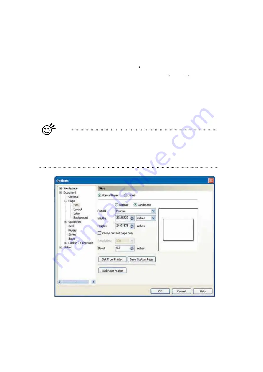
3)  From the primary menu, click LAYOUT 

PAGE SETUP. 

4)  From the navigation bar on the left, click DOCUMENT 

PAGE 

SIZE. 

5)  Ensure that NORMAL PAPER and LANDSCAPE are selected. 

6)  

Ensure the Paper Width and Height dimensions match the work table dimensions 

of 640 mm (25.197 inches) and 460 mm (18.110 inches) or 740 mm (29.134 

inches) x 460  mm (18.110 inches). 

7)  Click OK to end the paper size adjustment.

Tip

Instead of manually selecting the Landscape and setting the Paper Width and 

Height, you can simply click the Set From Printer function and CorelDraw will 

automatically set the proper orientation and dimensions based on the work 

table. (You MUST have the LaserPro S290LS set as the default printer prior to 

doing this.) 

Summary of Contents for S290LS Series

Page 1: ...www delinit by...

Page 2: ......

Page 3: ...nce Motion System the S290LS is clearly on the cutting edge of all laser systems GCC understands that a creative technical background is the key to successful growth in the ever changing information e...

Page 4: ......

Page 5: ...ectivity Setup 33 4 2 Graphics Software Setup 38 4 2 1 Recommended Computer Configuration 38 4 2 2 Installation of the LaserPro Print Driver 38 4 2 3 Using Parallels Desktops for MAC OS 40 4 2 4 Using...

Page 6: ...tBOX Option 118 7 5 Rotary Chuck 121 7 6 SmartGUARD Fire Alarm Option 126 Chapter 8 130 Basic Maintenance 130 8 1 Suggested Cleaning and Maintenance Supplies 131 8 2 Maintaining the Work table and Mot...

Page 7: ...232001410G 10 3 1 Chapter 1 Safety Principles of a DPSS Fiber Laser Safety Ratings The Safety Interlock System Safety Labels Safety Measures Operating Environment...

Page 8: ...the operator to see the exact location where the laser beam will fire Even though the LaserPro S290LS is equipped with the most powerful laser to date through proper usage and taking necessary hardwar...

Page 9: ...e labels are not to be modified in any way or removed for any reason Please familiarize yourself with the specific labels and their locations on the machine Below is a list of all the safety labels an...

Page 10: ...232001410G 10 6...

Page 11: ...der normal functioning conditions However as a precaution Laser Path Warning Label are affixed on possible laser paths and operators should be aware of the possibility of injury while machine is opera...

Page 12: ...Label This label indicates the emergency stop button You can find this label on the right upper side of the machine Aperture warning stickers mirror This label indicates the laser path Normally you c...

Page 13: ...ty of the machine Resulting debris from laser cutting are very dangerous and may cause fire hazard y DO NOT leave debris and scraps inside laser machine after job finished Must keep machine clean afte...

Page 14: ...ur machine will operate effectively and safely over a long period of time 1 6 Operating Environment Please follow the guidelines when considering a suitable location to set the LaserPro S290LS Imprope...

Page 15: ...sential requirements of the Directive has been based on elements of z EN ISO 12100 2010 Safety of machinery General principles for design Risk assessment and risk reduction z EN ISO 11553 1 2008 Safet...

Page 16: ...232001410G 11 12 2 Chapter 2 Unpacking Contents Unloading Unpacking Repacking Contents and Accessories Checklist...

Page 17: ...etal crates for GCC LaserPro laser engravers including Sprit Spirit LS Spirit GLS and S290LS Other models will change to metal packing crate in the near future For years GCC LaserPro has been dedicate...

Page 18: ...crate close to the desired working location of the machine Unpack following the steps below Step 1 Remove the 6 metal clips that secures the top panel to the crate by using a flathead screw driver St...

Page 19: ...232001410G 11 15 Step 3 Use a flathead screwdriver to remove the brackets that secures the bars in place...

Page 20: ...232001410G 10 16 Step 4 Remove the top bars Step 5 Use a flathead screwdriver to pry loose the side brackets and remove them...

Page 21: ...232001410G 11 17 Step 6 Pull the front panel and lower it to an angle of about 45 degrees and then pull it away from the crate Do the same for the rear panel...

Page 22: ...232001410G 10 18 Step 7 Remove the left and right panels in the same way after the front and rear panels have been removed Step 8 Unbuckle and remove the belts that holds the machine in place...

Page 23: ...Philips screwdriver to remove the brackets that holds the machine in place Step 10 Position the ramps as shown below and the machine can now be pushed off the base board via the ramps The ramps are fo...

Page 24: ...rd and carefully push the machine onto the iron pallet NOTE More than one person may be needed when loading and unloading the shipping crate in order to avoid body injury or damage to the machine Step...

Page 25: ...232001410G 11 21 Step 3 Insert four side boards on the slot of bottom plate Step 4 Fix the four side boards by four corner brackets...

Page 26: ...232001410G 10 22 Step 5 Place the top cover on the top of the machine and fix it with the fixers The machine is now repacked and ready for shipping...

Page 27: ...llowing items are missing immediately contact your local GCC distributor ITEM QUANTITY Cleaning Kit Cotton 1 Lens Cleaner Solution 1 Lens Tissue 1 Power Cord US EU AU 2 each USB Cable 1 LAN Cable 1 Fo...

Page 28: ...232001410G 10 24 3 Chapter 3 Mechanical Overview Front View Top View Right Profile View Left Profile View Rear View www delinit by...

Page 29: ...self with this section regarding the mechanical overview of the LaserPro S290LS References will be made back to the different parts of the LaserPro S290LS in later sections 3 1 Front View 3 2 Top View...

Page 30: ...232001410G 10 26 3 3 Right Profile View 3 4 Left Profile View LAN Port USB Port Power Cable Inlet Power On Off Switch Access Panel Mirror 1...

Page 31: ...232001410G 10 27 TM 3 5 Rear View SmartLID Operation Handles Ventilation Openings SmartEXT TM Pass Through Rear Door Laser Access Panel...

Page 32: ...4 Setup and Installation Machine Setup Powering Up the Machine Connecting the Computer Graphics Software Setup Recommended Computer Configuration Installation of the LaserPro USB Driver Installation o...

Page 33: ...ment wheel is located underneath the control panel 4 1 2 Connecting the Computer The LaserPro S290LS Series can communicate with a computer through a USB Port or LAN Port connection interface Regardle...

Page 34: ...Step 1 Connect LAN cable to the LAN port of GCC laser engravers and turn on machine Step 2 Navigate the control panel through F4 Function Machine Setting LAN Setup Wizard IP Address Step 3 Go to Windo...

Page 35: ...232001410G 10 31...

Page 36: ...232001410G 10 32...

Page 37: ...control panel through F4 Function Machine Setting LAN Setup Wizard DHCP OFF Step 3 Navigate the control panel through F4 Function Machine Setting LAN Setup Wizard IP Address Step 4 Enter 192 168 3 X X...

Page 38: ...4 TCP IPv4 and click Properties to open up the setting window Step 7 Enter the IP address and Subnet mask setting values and choose OK Note the IP address 192 168 3 X X value can be 1 255 while can t...

Page 39: ...Device and Printers of computer and right click on the laser machine printer choose Printer Properties Step 9 Select Add Pot under Ports tab and follow the instruction to enter the TCP IP information...

Page 40: ...232001410G 10 36...

Page 41: ...232001410G 10 37...

Page 42: ...following minimum requirements Computer CPU Pentium 90 or equivalent or greater RAM 32 MB or higher HDD 1 2 GB Hard Drive or greater SVGA 15 Super VGA Monitor On Board Parallel Mode Enabled from moth...

Page 43: ...Yes or No if you want to use this printer as the default printer and click Next to continue NOTE 10 At the Printer Sharing screen select Do not share this printer and click Next to continue 11 Select...

Page 44: ...e which allows you to install Windows OS in MAC computers and run Windows based software under MAC computer and output with GCC print driver 1 Purchase Parallels Desktops on its official website 2 Ins...

Page 45: ...4 Enter your Mac OS X User Name and Password then press OK 5 Press Active 6 Press OK when activation is complete...

Page 46: ...7 Register Parallels Desktop 8 Press Register and OK to complete the installation of Parallels Desktop 9 Open Parallels Desktop in the Applications folder then choose File New...

Page 47: ...10 Press Install Windows from DVD or image file then press continue to install windows OS 11 Select CD ROM drive with the Windows installation CD 12 Enter the Windows OS product key...

Page 48: ...ete the windows OS installation procedure will start automatically 15 Windows OS installation is complete then you can refer to 4 2 5 Installation of the LaserPro Print Driver to install GCC LaserPro...

Page 49: ...LaserPro machine 1 Start drawing 2 Delete border and title block by right clicking on sheet1 and selecting delete 3 Set sheet size to match working area of engraver Engraver working area can be found...

Page 50: ...tch 5 Engraving a Finish sketch b Right click on sketch and select properties c Line Type By Layer d Line Weight By Layer e Set color to match one of the 16 colors available in the pen tab of the wind...

Page 51: ...ith all the cuts to do so properly 4 2 8 Using eCut Plug in with GCC LaserPro machine eCut is an inexpensive and powerful plugin work under CorelDRAW or Illustrator software with GCC laser systems It...

Page 52: ...Chart Graphic Control Panel Function Pages The LaserPro S290LS Print Driver Page Setup and Orientation Color Management Using the LaserPro S290LS Print Driver LaserPro S290LS Print Driver Options Page...

Page 53: ...ne If the key switch is turned to the OFF position the laser will be disabled meaning that the laser will not fire although the XY motion system will still move 5 1 2 Adjusting the LCD Display Screen...

Page 54: ...hen either the top lid or external pass through doors on the LaserPro S290LS are open or improperly closed Power The power light will illuminate when the LaserPro S290LS is powered on Laser The laser...

Page 55: ...al the directional buttons cycle through the various selections while the directional buttons adjust the value of that particular selection Enter Confirms the current selection Start Stop Allows you t...

Page 56: ...Control Panel Navigation Chart Main Work Page Carriage Work Table Adjustment Page Functions Page File Management Page Machine Settings Page Machine Information Page Select Lens Page Link DLink Page T...

Page 57: ...nctions of the control panel This will be the page that is displayed when you are processing your jobs This page contains specific job information such as the current job s name Speed Power Freq DPI p...

Page 58: ...and X axis of the laser carriage Carriage Work Table Adjustment Page Relevant Buttons Function F1 Back Back to previous page F3 Down Manually decrease the height of the work table Z axis F4 Up Manual...

Page 59: ...ated by moving the carriage by hand and pressing enter to save the positions indicated by the red pointer After all points are set the carriage will move to the center of the two entered points and th...

Page 60: ...o Focus Set Table Down Set Red Beam Carriage Lock Set Command Mode Save Position Flash Memory Set File Save Mode Set Vector Mode Tune Image Power Set Laser Wattage Set Fine Mode Other Reset Machine In...

Page 61: ...ink DLink Page to set and arrange multiple loaded jobs into a single job queue for processing File Management Page Relevant Buttons Function F1 Back Back to previous page F2 Link Go to the Link DLink...

Page 62: ...ns to the right of your file names The first column to the right of your job file name displays the job number of the previous file in the job queue sequence The second column after the file name disp...

Page 63: ...d Freq settings of the selected job In addition you will be able to go to the File Management Edit Page from this menu to change raster vector speed and power settings for the selected job File Inform...

Page 64: ...your raster or vector settings for the selected job as well as setting the number of times to repeat the process of the selected job Repeat Num File Management Edit Page Relevant Buttons Function F1...

Page 65: ...correspond to the same settings found on the LaserPro S290LS print driver This page allows you to easily adjust these values to make immediate adjustments while processing your loaded jobs even when y...

Page 66: ...on the LaserPro S290LS print driver This page allows you to easily adjust these values to make immediate adjustments while processing your loaded jobs even when you have disconnected your computer fro...

Page 67: ...Red Beam Carriage Lock Set Command Mode Save Position Flash Memory Set File Save Mode Set Vector Mode Tune Image Power Set Laser Wattage Set Fine Mode Other and Reset Machine Setting Page Relevant Bu...

Page 68: ...s after you have made the proper changes Now by pressing the Auto Focus button the LaserPro S290LS will conduct auto focus accordingly using the new lens The default setting is 4 0 Lens 2 0 4 0 Go to...

Page 69: ...o manually set the default auto focus distance vertical height of the worktable Z axis when the Auto Focus button is pushed Tune Auto Focus Page Relevant Buttons Function F1 Back Back to previous page...

Page 70: ...ve down and remove objects on table Pressing the Enter key at this point will confirm the prompt to move the work table to its lowest position If the Table Down is set to NO then the LaserPro S290LS w...

Page 71: ...red dot laser pointer on the laser carriage Enabling this function will indicate the exact area the engraving laser will fire upon Red Beam YES NO Set Red Beam Page Relevant Buttons Function F1 Back B...

Page 72: ...ble to manually move the laser carriage along the X and Y axis by hand with the top door open Whereas setting the Carriage Free to NO will lock the laser carriage and movement or positioning can only...

Page 73: ...llustrator and more Whereas HPGL mode is a less common output format generated from some RIP applications signage industry Regardless of which format you will be working with both output formats are s...

Page 74: ...osition to be the origin for subsequent jobs Tip This is an excellent function to use when you are processing identical items or engraving relatively smaller objects positioned away from the default s...

Page 75: ...r processing Setting File Save to NO will automatically and immediately delete each job file from the LaserPro S290LS after the engraving or cutting process Setting File Save to YES will retain all jo...

Page 76: ...ath result in smooth edge higher speed while less precise in scale factor whereas setting Smoothing to NO the curve will move in more precision scale less smooth path and slower speed Acceleration Mod...

Page 77: ...Disable the function The Time function is to determine after how long the laser machine is idle it will enter in power saving automatically The default time is 4 minutes The Enter Standby function wil...

Page 78: ...The Adjust image offset function allows you to align the position of raster object against vector outputs Adjust Image Offset 0 0 mm Image Offset Tuning Page Relevant Buttons Function F1 Back Back to...

Page 79: ...ck to previous page F4 More To display information on next page U V Directional Scroll the display page Start Stop Back to Main Work Page Auto Focus Initiate the auto focus function S T Manual Focus B...

Page 80: ...uter to laser machine for processing jobs When selecting the DHCP to ON the network is set tup to dynamic IP address the IP address will automatically retrieve from network while DHCP OFF is to apply...

Page 81: ...Y Z Directional Cycle DHCP between NO OFF or move between tabs on IP address settings U V Directional Scroll between menu options or change the numbers of IP address settings Start Stop Back to Main W...

Page 82: ...ible notification when jobs are complete The Air Delay setting allows you to specify the delay in seconds of the SmartAIR air assist after the point of laser firing Language ENGLISH others dependent o...

Page 83: ...set Page will restore machine settings back to factory default Press ENTER to confirm the change and restart the machine Reset Page Relevant Buttons Function F1 Back Back to previous page Directional...

Page 84: ...you to view information regarding the system such as the GCC logo machine name firmware version and other information Machine Information Page Relevant Buttons Function F1 Back Back to previous page D...

Page 85: ...u may set it up through the graphics software as well The following example takes CorelDRAW to demonstrate how to set up LaserPro S290LS as the Printer 1 From the primary menu click FILE PRINT SETUP 2...

Page 86: ...CUMENT PAGE SIZE 5 Ensure that NORMAL PAPER and LANDSCAPE are selected 6 Ensure the Paper Width and Height dimensions match the work table dimensions of 640 mm 25 197 inches and 460 mm 18 110 inches o...

Page 87: ...olor Management page Disable Color Management or set Color Management to Off CorelDRAW Example Color Management The following is an example of how to properly disable Color Management in the graphics...

Page 88: ...ptions After you have setup your image design or text to be engraved in your software application you can access the LaserPro S290LS print driver by going to FILE PRINT PROPERTIES NOTE For this screen...

Page 89: ...would like to achieve Black White Select this mode when using clipart images or drawings with several colors shades of gray or many outlines This mode outputs in a method similar to that of a black a...

Page 90: ...k White mode will enable the Raster page on the LaserPro S290LS Print Driver Manual Color Fill Select this mode when you would like to designate specific power and speed settings and link them to cert...

Page 91: ...e to the machine and will need to be initialized from the LaserPro S290LS control panel SmartACT Options Page DEFAULT SETTING Unselected SmartACT reduces the amount of time it takes to process a job b...

Page 92: ...232001410G 10 88 file in order to activate the Preview function A filename will be prompted After entering the filename and pressing ok the Preview screen will be shown...

Page 93: ...ension LOAD This function allows you load previously saved print driver parameters or LaserPro parameter database ORIGINAL This function will load the print driver s original factory parameter setting...

Page 94: ...ip LaserPro material database settings allow you easy to load the several parameters If you are loading LaserPro parameter database as your operating parameter please direct load from several build in...

Page 95: ...signated laser setting rather than as a color As an example a black and white image will use only one power and speed laser setting Black An image that is made up of black red and blue colors will be...

Page 96: ...lider controls the laser s speed during operation engraving speed with settings ranging from 0 1 100 The maximum laser processing speed of the S290LS is 80 inches per second therefore a setting of 100...

Page 97: ...box will enable the SmartAIR air assist function for that particular pen color As an example if you are performing a combination of both surface raster engraving job and deep vector cutting on a mater...

Page 98: ...e determined by a combination of power and speed Slower speeds at higher power will produce deeper cuts and engravings whereas higher speeds at lower power will produce shallower cuts and engravings W...

Page 99: ...choose if we want to operate the laser under Pulse mode or C W mode Pulse mode In general higher power can be achieved with Pulse mode since higher peak power can be achieved C W mode C W mode is gre...

Page 100: ...to adjust the slider by 1 if the final output is 1 unit increment shorter or 1 if the final output is 1 unit increment longer than your graphic design setting Position Modes Advanced Page DEFAULT SET...

Page 101: ...rtCENTER function is a great tool for users whose jobs often require engraving on specific locations Tip It is highly recommended you enable the red dot laser pointer when setting adjusting the Positi...

Page 102: ...automatically direct the laser to cut from the inner most vector shape and move outwards Cutting Path Optimization This is a setting that will minimize your process time When selected the print drive...

Page 103: ...r function simultaneously then the Border Thickness value must be less than the Distance value specified in the Cluster setting Enhanced Vector Mode Advanced Page DEFAULT SETTING Unselected This setti...

Page 104: ...e precision you will need to adjust the image tuning setting To adjust this setting we recommend that you engrave a small black square design as a sample and use a magnifying glass to view the engrave...

Page 105: ...d right picture Extend Paper Page DEFAULT SETTING Unselected If you are processing a very large area requiring the maximum work table area you will want to enable this mode Enabling this mode will ext...

Page 106: ...d Traditional Japanese and German 5 2 3 6 LaserPro S290LS Print Driver Raster Page Contrast Raster Page DEFAULT SETTING 0 This provides a quick and easy way to immediately adjust the contrast of an en...

Page 107: ...g via the dithering method This mode will allow you to select the Pattern Type and Dithering Matrix and Enhanced Dithering o Pattern Type Dot Bayer Corner 45 Degree DEFAULT SETTING Dot Each pattern ty...

Page 108: ...m three diffusion types Floyd Stucki and Jarvis o Diffusion Type Floyd Stucki Jarvis DEFAULT SETTING Floyd Each diffusion type presents the shade of image as different spread halftones instead of dots...

Page 109: ...232001410G 10 105 6 Chapter 6 Engraving and Cutting Techniques Raster Engraving Vector Cutting To modified image settings of a picture for better engraving quality...

Page 110: ...ntinuous firing of the laser to cut out various shapes When performing vector cutting operations imagine the laser head as a pair of scissors cutting out the lines specified in your design An example...

Page 111: ...cters outline thickness to the thinnest width by right clicking on the selected text select Properties Click on the Outline tab and change the Width to its thinnest dimension Click on OK to apply the...

Page 112: ...232001410G 10 108 6 Change the Bitmap settings by setting Color to Grayscale 8 bit and Resolution to 300 dpi and click OK 7 Finally Invert the image by selecting Effects Transform Invert...

Page 113: ...232001410G 10 109 8 Now you are ready to output the modified image by clicking File Print...

Page 114: ...und the engraved area Then the Waveforms can be switched to a long high energy pulse with its higher material removal rate Throughout this process a short pulsed Waveforms is regularly used to clean t...

Page 115: ...different colors can be marked by laser Recommended parameter settings for 40HHS model is low speed range under 15 moderate power range 28 55 and fixed 3000 DPI with waveforms selection 0 1 2 3 4 5 Pi...

Page 116: ...stroy the metal surface only 125kHz is recommended for frequency 3 Low DPI setting below 1500 DPI will mark the material with different gray levels only not colorful contrast high DPI is recommended N...

Page 117: ...232001410G 10 113 7 Chapter 7 Optional Items Fume Extraction System Air Compressor Focus Lens SmartBOX Rotary Chuck SmartGUARD Fire Alarm...

Page 118: ...nited States and Canada To purchase a LaserPro Fume Extraction System contact your local authorized GCC distributor INSTALLATION Self Assembled Unit 1 Purchase an exhaust system at your local industri...

Page 119: ...ul and potentially damaging moisture from the laser optics maximizing life of the laser optics In addition the air compressor provides an optimal air flow to the SmartAIR nozzles to minimize flaming s...

Page 120: ...ted below 5 Plug the air compressor s power cord A into the AC internal power socket 6 Plug the female end of power cord B to the AC internal power socket and the male end to an external power outlet...

Page 121: ...se refer to the LaserPro S290LS PEN page of print driver section of this manual for details on how to enable and configure air assist functionalities 7 3 Focus Lens Option GCC offers two different foc...

Page 122: ...d smoke to minimize excess buildup on the machine worktable and your project The SmartBOX allows you to maintain a clean worktable and minimizes backside burning of your media whether you are working...

Page 123: ...asks INSTALLATION OPERATION Cutting Box and Material Support Stands 1 In order to use the cutting box along with the material support stands you must first remove the honeycomb table from the cutting...

Page 124: ...ting of the metal guard 7 Now position the included material support stands so they support the thick firm material you will be working with while avoiding the laser path In other words avoid placing...

Page 125: ...ATION 1 Turn off the power of the engraver 2 Set the Rotary Chuck onto the working table so that the bottom mounting screws correspond to the positional holes on the working table In addition the clam...

Page 126: ...lic claws Simply insert the two metal pins into the holes on the turn dial and turn it to widen or tighten the claws to hold the engraving object There are two different ways that the rotary attachmen...

Page 127: ...ble clamps along the groove with machine oil regularly after each use The rear end of the Rotary Chuck also can be locked or unlocked to slide its position by using an Allen key as shown below Dial th...

Page 128: ...ble rear end Adjust the leveling screws on the rear end of Rotary Chuck to make sure the work object is centering to the clamping end thus work piece is horizontally leveling to the laser carriage in...

Page 129: ...of your work piece in this field Again remember the proper diameter value would be the diameter location on your work piece you will be engraving c Under Rotary Parameter the Offset value represents d...

Page 130: ...em that can be set to notify the operator through audio warnings and automatically shut down the laser firing as a safety precaution INSTALLATION If you have purchased your system with SmartGUARD then...

Page 131: ...232001410G 10 127 2 Remove the protective cover 3 Assemble the SmartGUARD at the indicated location as shown below Front View Top View...

Page 132: ...tional key Left or Right to enable the SmartGUARD device or disable it Sensitivity Press directional key left or right to set the sensitivity of SmartGUARD There are five sensitivity settings 1 3 5 7...

Page 133: ...tion up or down when fire alarm is initiated The default is YES the lens carriage will move to opposite direction when a fire detected SmartGUARD Setting Page Relevant Butto Function F1 Back Back to p...

Page 134: ...nance Supplies Maintaining the Work table and Motion System Accessing the Work table and Motion System Cleaning the Work table and Motion System Lubrication of the Y Rails Cleaning the Optics System R...

Page 135: ...system if you do not turn off and unplug the LaserPro S290LS before cleaning Always turn off and unplug the LaserPro S290LS before cleaning 8 1 Suggested Cleaning and Maintenance Supplies The recommen...

Page 136: ...ed open by using the handles from the rear side of the LaserPro S290LS Lift the lid to the maximum indicated by a small click to engage the latch as shown in the picture below 2 Manually lock the Smar...

Page 137: ...ll purpose cleaner alcohol or acetone to a paper or cotton towel to clean the working table 4 Apply a soap solution all purpose cleaner or alcohol to a paper or cotton towel to wipe down the rails of...

Page 138: ...on opening inside the linear bearing and move the lens carriage to smooth the grease and movement 4 Repeat the step 3 till the grease is full out of the linear bearing 5 Repeat the step 3 and 4 to the...

Page 139: ...r guide 2 Use clean oil on cotton swab and then grease on linear guide including top bottom and surface of linear guide NOTE Always clean and lubricate the rails after working with materials that prod...

Page 140: ...g steps to clean them The following section will illustrate the location of the four mirrors found in the machine for cleaning Mirror 1 This mirror is located inside the bottom left access panel of th...

Page 141: ...ptics holder after cleaning 5 Tighten the thumbscrew 6 Replace and secure the black dust cover Mirror 3 1 Loosen the thumbscrew holding mirror 3 in place 2 Clean the lens in the proper manner 3 Place...

Page 142: ...he mirrors 1 Hold the mirror with the reflective side up without touching the reflective side of the mirror DO NOT apply any finger pressure or any other cleaning solutions to the mirror surface 2 Dra...

Page 143: ...leaning the Focal Lens 1 Remove the three thumbscrews front face of the laser head securing the laser carriage panel and remove the laser carriage panel to reveal the focal lens 2 Carefully pull out t...

Page 144: ...9 232001410G 10 140 Chapter 9 Basic Troubleshooting...

Page 145: ...he control panel 3 Check if the laser power connector is connected 4 For safety purposes the laser will not fire when the top lid or the front door is open unless the door sensors are defeated by shor...

Page 146: ...10 232001410G 1 1 142 Chapter 10 Appendix Glossary LaserPro S290LS Specification Sheet...

Page 147: ...e chips or in the case of EEROM by special procedure Frequency Adjusting the Frequency determines the peak power of the laser which affects the color variation and depth of the laser marking A lower f...

Page 148: ...roughput See dealer or visit www gccworld com for more details z Caution Use of controls or adjustments or performance of procedures other than those specified herein may result in hazardous radiation...

Reviews:

Related manuals for S290LS Series