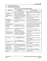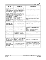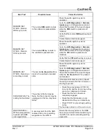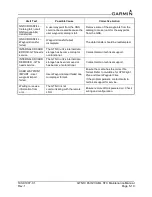
190-01007-C1
GTN Xi Part 23 AML STC Maintenance Manual
Rev. 1
Page 4-10
4.6.2 GTN Xi TVS2 Assembly Check (GTN Xi #1 Only)
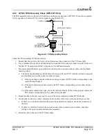
The TVS assembly (refer to Section 6.9) and fuse on the power bus side of GTN Xi #1 must be inspected.
Verify operation of all four TVSs prior to replacing any failed TVS.
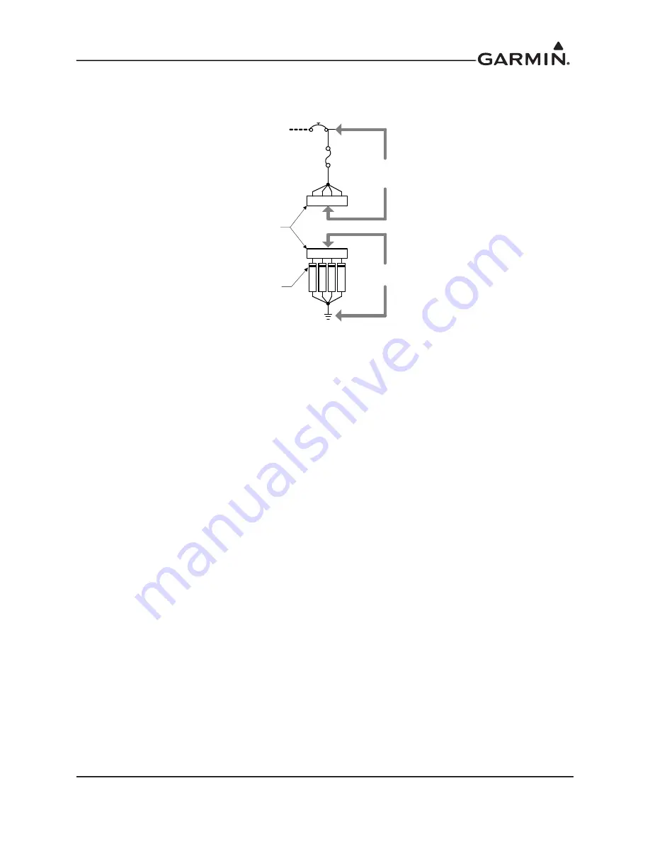
Figure 4-1 TVS Assembly Check
Check the TVS assembly (TVS2) as follows:
1. Ensure that the power to the bus is off and disconnect the connector in the TVS assembly.
2. Use a multimeter to perform a diode check between the first connector contact (socket contact on
the first TVS) and ground. Refer to Figure 4-1 for additional details.
3. The meter should indicate open with the red lead on the connector socket contact and the black
lead on ground.
a. The meter should indicate a diode drop of between 2.0V and 2.5V with the red lead on ground
and the black lead on the connector socket contact.
i) If the diode drop is outside of the above range, replace the TVS diode corresponding to the
contact being checked.
ii) If the meter indicates a short, replace the TVS diode corresponding to the contact being
checked.
iii) If the meter indicates an open, check the wiring for faults. If the wiring is good, replace the
TVS diode corresponding to the contact being checked.
4. Repeat checks in the previous step for each of the three remaining contacts/TVS diodes.
5. On the other connector, verify continuity between each of the four contacts and the power bus.
a. If there is no continuity between the power bus and all four contacts, check the continuity of
the fuse.
b. If there is continuity between the power bus and some contacts, but not others, check the
wiring to the open contacts and repair as necessary.
6. Reconnect the connector in the TVS assembly.
5A
TVS DIODE CHECK
STRIPE ON
TVS INDICATES
CATHODE SIDE
TO GTN Xi #1
T
V
S
T
V
S
T
V
S
T
V
S
1 2 3 4
1 2 3 4
TVS ASSEMBLY
CONNECTOR
CONTINUITY CHECK

