


G1000 / GFC 700 System Maintenance Manual - 300/B300 Series King Air
Page 3-5
190-00716-01
Revision 1
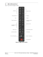
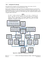
3.5
G1000 Normal Mode
To start the G1000 system in Normal Mode:
1.
With a ground power unit connected to the external power receptacle, set the BAT and EXT PWR
switches to ‘ON’. The following G1000 equipment is powered:
•
PFD displays & MFD display
•
GRS 77 AHRS Units
•
GDC 7400 Air Data Computers
•
GIA 63W Integrated Avionics Units
•
GEA 71 Engine/Airframe Units
•
GCU 477 FMS Control Unit
•
GMC 710 Autopilot Control Unit
•
GSA Servos
•
GMA 1347D Digital Audio Panel #1
•
GSD 41 Data Concentrator (Optional)
2.
Set the AVIONICS MASTER switch to ‘ON’. The following G1000 equipment is powered:
•
GMA 1347D Digital Audio Panel #2
•
GDL 69A Datalink Unit
•
GWX 68 Weather Radar Unit
•
GTS 8XX Traffic System (Optional)
•
GTX 33 Mode S Transponders (Optional)
•
GDL 59 / GSR 56 Wi-Fi/Satellite (Optional)
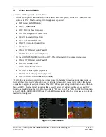
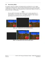
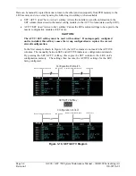
The G1000 system is now powered in the normal mode. In the normal operating mode, data fields that
are invalid have large red X’s through them. A valid field does not display a red X. Allow the displays
to initialize for approximately one minute. The GDC 7400s require a longer initialization period than do
the other LRUs. During normal operation, this causes the airspeed, altitude, vertical speed, and OAT
fields to be invalid during the first ~40-60 seconds of PFD power-up
.
The PFDs and MFD will function
as specified in the G1000 300/B300 Series Cockpit Reference Guide when the system has been correctly
installed and configured.
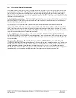
Figure 3-7, Normal Mode
Summary of Contents for Cessna Caravan G1000
Page 2: ...This page intentionally left blank...
Page 89: ......


