G1000 / GFC 700 System Maintenance Manual - 300/B300 Series King Air
Page 7-21
190-00716-01
Revision 1
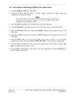
11.
The result of the pitch/roll offset compensation is displayed on the PFD. If successful, the AHRS
records the required pitch and roll offsets, informs the operator of a successful conclusion and
returns to normal operation.
12.
Press the ENT key on the PFD to conclude this procedure for GRS 77 #1.
13.
Repeat steps 1 through 6 for GRS 77 #2.
NOTE
The Magnetometer Calibration Procedure that follows in Section 7.7.4
(Calibration Procedure B) must be carried out at a site that is determined
to be free of magnetic disturbances. If it is unsure whether the site is
‘clean’, the technician should verify that the site is ‘clean’ by following
the guidance provided in Section 7.7.3. The technician may skip Section
7.7.3 if the site condition is acceptable.
7.7.3
Compass Rose Evaluation of Magnetic Disturbances for Magnetometer
Calibration Procedure (Optional)
NOTE
Typically, a compass rose is an acceptable location to perform the
magnetometer calibration procedure. However, because not all compass
roses are well maintained, even an existing compass rose should be
regularly evaluated using the method described here to determine if it is
free of magnetic disturbances. If evaluation of an existing compass rose
indicates that magnetic disturbances are present, then an alternative
location must be found to perform the Magnetometer Calibration
Procedure.
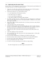
A G1000-equipped airplane that has completed the pitch/roll offset compensation procedure (Procedure
A-1, Section 7.7.2) can be used to evaluate a candidate site for magnetic disturbances and determine
whether it is a suitable location to perform the magnetometer calibration procedure. The magnetometer
calibration procedure itself contains the logic to simultaneously survey the location for magnetic
cleanliness while it is computing the magnetometer calibration parameters.
In order to evaluate a candidate site, the Magnetometer Calibration Procedure must be performed twice:
once turning clockwise around the site, and once turning counter-clockwise. Both times, the procedure
should be conducted as described in Section 7.7.4 of this document, with the exception of the direction of
turns around the site.
NOTE
Although Section 7.7.4 indicates that the Magnetometer Calibration
Procedure should be performed by making a series of clockwise turns
around the site, the procedure can also be performed by making counter-
clockwise turns for the purpose of evaluating the site for magnetic
disturbances.
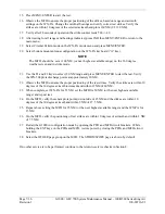
If the PFD displays the “CALIBRATION SUCCESSFUL / SITE IS CLEAN” message upon completion
of the Magnetometer Calibration Procedure in each clockwise and counter-clockwise direction, then the
candidate site is sufficiently free of magnetic disturbances and is acceptable for performing the
Magnetometer Calibration Procedure. It is important to obtain successful result in both the clockwise and
counter-clockwise directions to ensure that the magnetometer sweeps over a large enough area at the
candidate site.
If the PFD displays either the “MAG FIELD AT SITE NOT UNIFORM” or “MAG FIELD AT SITE
DIFFERS FROM IGRF MODEL” message upon completion of the Magnetometer Calibration Procedure
in either of the two directions, then the site contains magnetic disturbances that are too large.
Summary of Contents for Cessna Caravan G1000
Page 2: ...This page intentionally left blank...
Page 89: ......

