


Garmin G5 Install Manual & Pilot's Guide
190-02072-00 Rev. E
48
Unit Installation
Installation Manual
Pilot's Guide
Appendix
Index
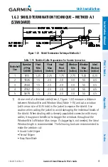
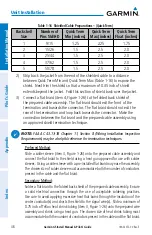
Table 1-16 Shielded Cable Preparations – (Quick Term)
Backshell
Size
Number of
Pins Std/HD
Quick Term
Min (inches)
Quick Term
Max (inches)
Quick Term
Float (inches)
1
9/15
1.25
2.25
1.75
2
15/26
1.5
2.5
2.0
3
25/44
1.5
2.5
2.0
4
37/62
1.5
2.5
2.0
5
50/78
1.5
2.5
2.0
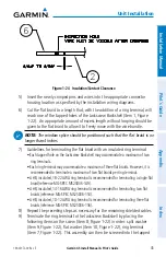
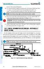
2) Strip back the jacket from the end of the shielded cable to a distance
between Quick Term Min and Quick Term Max (Table 1-16) to expose the
shield. Next trim the shield so that a maximum of 0.35 inch of shield
extends beyond the jacket. Fold this section of shield back over the jacket.
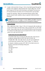
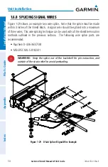
3) Connect a flat braid (item 4, Figure 1-26) to the folded back shield of
the prepared cable assembly. The flat braid should exit the front of the
termination and towards the connector. The flat braid should not exit the
rear of the termination and loop back towards the connector. Make the
connection between the flat braid and the prepared cable assembly using
an approved shield termination technique.
NOTE:
FAA AC 43.13-1B Chapter 11, Section 8 (Wiring Installation Inspection
Requirements) may be a helpful reference for termination techniques.
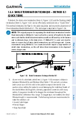
Preferred Method
:
Slide a solder sleeve (item 3, Figure 1-26) onto the prepared cable assembly and
connect the flat braid to the shield using a heat gun approved for use with solder
sleeves. Using a solder sleeve with a pre-installed flat braid may ease the assembly.
The chosen size of solder sleeve must accommodate both the number of conductors
present in the cable and the flat braid.
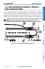
Secondary Method
:
Solder a flat braid to the folded back shield of the prepared cable assembly. Ensure
a solid electrical connection through the use of acceptable soldering practices.
Use care to avoid applying excessive heat that burns through the insulation of the
center conductor(s) and shorts the shield to the signal wire(s). Slide a minimum of
0.75 inch of Teflon heat shrink tubing (item 3, Figure 1-26) onto the prepared wire
assembly and shrink using a heat gun. The chosen size of heat shrink tubing must
accommodate both the number of conductors present in the cable and the flat braid.
Summary of Contents for Approach G5 - GPS-Enabled Golf Handheld
Page 1: ...G5 Install Manual Pilot s Guide ...
Page 2: ...Blank Page ...
Page 3: ...INSTALLATION MANUAL PILOT S GUIDE APPENDIX INDEX ...
Page 4: ...Blank Page ...
Page 16: ...Garmin G5 Install Manual Pilot s Guide 190 02072 00 Rev E iv Table of Contents Blank Page ...
Page 237: ...Garmin G5 Install Manual Pilot s Guide 190 02072 00 Rev E Blank Page ...