Garmin G5 Install Manual & Pilot's Guide
190-02072-00 Rev. E
167
Pilot's Guide
Installation Manual
Pilot's Guide
Appendix
Index
3
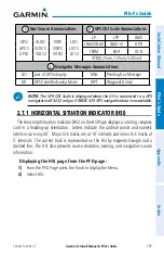
Nav Source Annunciations
11
GPS CDI Scale Annunciations
GPS/
GPS1/
GPS2
VLOC/
VLOC1/
VLOC2
VOR/
VOR1/
VOR2
LOC/
LOC1/
LOC2
LP
LPV
LNAV
LNAV/VNAV
LNAV+V
APR
TERM
ENR
OCN
VFR (0.25nm, 1.25nm, 5.00nm)
5
Navigator Messages Annunciations
LOI
Loss of GPS Integrity
MSG
Pending Nav Message
DR
GPS Dead-Reckoning Mode
WPT
Waypoint Arrival
NOTE:
The VFR CDI Scale is displayed when the G5 is connected to a GPS
navigator via RS-232 only, or if ARINC 429 GPS navigation data is unavailable.
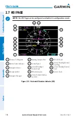
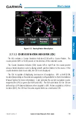
2.7.1 HORIZONTAL SITUATION INDICATOR (HSI)
The Horizontal Situation Indicator (HSI) on the HSI Page displays a rotating compass
card in a heading-up orientation. Letters indicate the cardinal points and numeric
labels occur every 30˚. Major tick marks are at 10˚ intervals and minor tick marks at
5˚ intervals. The current track is represented on the HSI by magenta triangle and a
dashed line. The HSI also presents course deviation, bearing, and navigation source
information.
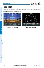
Displaying the HSI page from the PFD page:
1)
From the PFD Page press the Knob to display the Menu.
2)
Select HSI.
Summary of Contents for Approach G5 - GPS-Enabled Golf Handheld
Page 1: ...G5 Install Manual Pilot s Guide ...
Page 2: ...Blank Page ...
Page 3: ...INSTALLATION MANUAL PILOT S GUIDE APPENDIX INDEX ...
Page 4: ...Blank Page ...
Page 16: ...Garmin G5 Install Manual Pilot s Guide 190 02072 00 Rev E iv Table of Contents Blank Page ...
Page 237: ...Garmin G5 Install Manual Pilot s Guide 190 02072 00 Rev E Blank Page ...

