Garmin G5 Install Manual & Pilot's Guide
190-02072-00 Rev. E
97
Unit Installation
Installation Manual
Pilot's Guide
Appendix
Index
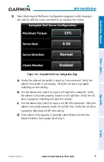
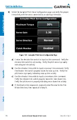
7)
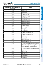
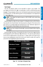
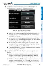
Select the Yaw Damper Configuration page and verify the proper trim
activity with the servo connected to an auxiliary trim motor.
Figure 1-66 Yaw Damper Configuration Page
a)
Center the aircraft rudder trim switch to input no trim command. Verify
the rudder trim switch is not moving. Verify the yaw servo is properly
indicating no trim activity.
b)
Use the rudder trim switch to input a yaw right trim command. Verify
the rudder trim switch properly moves for yaw right trim. Verify the yaw
servo is properly indicating yaw right trim activity.
c)
Use the rudder trim switch to input a yaw left trim command. Verify
the rudder trim switch properly moves for yaw left trim. Verify the yaw
servo is properly indicating yaw left trim activity.
d)
If the rudder trim response is reversed, select Reverse for the Trim Motor
Direction, then repeat all of step 7.
8)
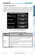
Select the Autopilot Roll Servo Configuration page to configure the servo
direction.
a)
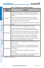
With the Servo Direction set to Normal, the servo arm should move
clockwise to cause a bank left aileron movement and the servo arm
should move counterclockwise to cause a bank right aileron movement.
b)
With the Servo Direction set to Reverse, the servo arm should move
clockwise to cause a bank right aileron movement and the servo arm
should move counterclockwise to cause a bank left aileron movement.
Summary of Contents for Approach G5 - GPS-Enabled Golf Handheld
Page 1: ...G5 Install Manual Pilot s Guide ...
Page 2: ...Blank Page ...
Page 3: ...INSTALLATION MANUAL PILOT S GUIDE APPENDIX INDEX ...
Page 4: ...Blank Page ...
Page 16: ...Garmin G5 Install Manual Pilot s Guide 190 02072 00 Rev E iv Table of Contents Blank Page ...
Page 237: ...Garmin G5 Install Manual Pilot s Guide 190 02072 00 Rev E Blank Page ...

