Garmin G5 Install Manual & Pilot's Guide
190-02072-00 Rev. E
49
Unit Installation
Installation Manual
Pilot's Guide
Appendix
Index
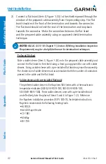
Teflon heat shrink tubing
Reference MIL-SPEC Teflon heat shrink tubing M23053/5-X-Y.
4) Insert the newly crimped pins and wires into the appropriate connector
housing location as specified by the installation wiring diagrams.
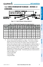
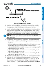
5) Cut the flat braid to a length that, with the addition of a ring terminal, will
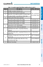
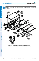
reach one of the tapped holes of the Jackscrew Backshell (item 1, Figure
1-22). An appropriate amount of excess length without looping should be
given to the flat braid to allow it to freely move with the wire bundle.
NOTE:
The window splice should be positioned such that the flat braid is no
longer than 4 inches.
6) Guidelines for terminating the flat braid with an insulated ring terminal:
• Each tapped hole on the Jackscrew Backshell may accommodate a maximum of two
ring terminals.
• Each ring terminal may accommodate a maximum of three flat braids. However, it is
recommended to terminate a maximum of two flat braids per ring terminal.
• A #8, insulated, 18-22 AWG ring terminal is recommended for terminating a single flat
braid (reference MIL-SPEC MS25036-149).
• A #8, insulated, 14-16 AWG ring terminal is recommended for terminating two flat
braids (reference MIL-SPEC MS25036-153).
• A #8, insulated, 10-12 AWG ring terminal is recommended for terminating three flat
braids (reference MIL-SPEC MS25036-156).
7) Repeat the preceding steps as necessary for the remaining shielded cables.
8) Terminate the ring terminal to the Jackscrew Backshell by placing the
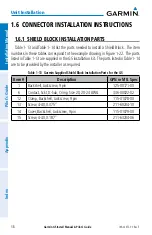
following items on the screw (item 8, Figure 1-22) in order: split washer
(item 9, Figure 1-22), flat washer (item 10, Figure 1-22), ring terminal (item
7, Figure 1-22). This assembly can then be screwed into the tapped holes
on the Jackscrew Backshell.
9) It is recommended to wrap the cable bundle with silicone fusion tape (item
11, Figure 1-22) at the point where the backshell clamp (item 12,
Figure 1-22) and backshell housing will contact the cable bundle.
NOTE:
Use of silicone fusion tape is at the discretion of the installer.
Summary of Contents for Approach G5 - GPS-Enabled Golf Handheld
Page 1: ...G5 Install Manual Pilot s Guide ...
Page 2: ...Blank Page ...
Page 3: ...INSTALLATION MANUAL PILOT S GUIDE APPENDIX INDEX ...
Page 4: ...Blank Page ...
Page 16: ...Garmin G5 Install Manual Pilot s Guide 190 02072 00 Rev E iv Table of Contents Blank Page ...
Page 237: ...Garmin G5 Install Manual Pilot s Guide 190 02072 00 Rev E Blank Page ...

