Garmin G5 Install Manual & Pilot's Guide
190-02072-00 Rev. E
43
Unit Installation
Installation Manual
Pilot's Guide
Appendix
Index
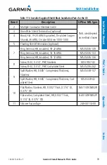
Individual solder sleeves and flat braid
Solder Sleeves:
Reference the following MIL-SPECs for solder sleeves:
• M83519/1-1
• M83519/1-2
• M83519/1-3
• M83519/1-4
• M83519/1-5
Flat Braid:
Flat braids should conform to the ASTMB33 standard for tin-plated copper wire
and be made up of 36 AWG strands to form an approximately 19-20 AWG
equivalent flat braid. A circular mil area range of 1000 to 1300 is required. The
number of individual strands in each braid bundle is not specified. Reference
MIL-SPEC flat braid QQB575F36T062.
NOTE:
Flat braid, as opposed to insulated wire, is specified in order to
allow for a visual inspection of the conductor as required for continued
airworthiness.
Secondary Method
:
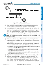
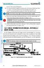
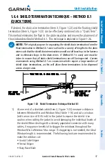
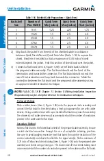
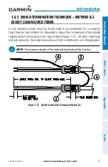
Solder a flat braid to the shield exposed through the window of the prepared
cable assembly. Ensure a solid electrical connection through the use of acceptable
soldering practices. Use care to avoid applying excessive heat that burns through
the insulation of the center conductor(s) and shorts the shield to the signal wire(s).
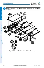
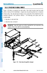
Slide a minimum of 0.75 inch of Teflon heat shrink tubing (item 3, Figure 1-23) onto
the prepared wire assembly and shrink using a heat gun. The chosen size of heat
shrink tubing must accommodate both the number of conductors present in the
cable and the flat braid.
Teflon heat shrink tubing
Reference MIL-SPEC Teflon heat shrink tubing M23053/5-X-Y.
Summary of Contents for Approach G5 - GPS-Enabled Golf Handheld
Page 1: ...G5 Install Manual Pilot s Guide ...
Page 2: ...Blank Page ...
Page 3: ...INSTALLATION MANUAL PILOT S GUIDE APPENDIX INDEX ...
Page 4: ...Blank Page ...
Page 16: ...Garmin G5 Install Manual Pilot s Guide 190 02072 00 Rev E iv Table of Contents Blank Page ...
Page 237: ...Garmin G5 Install Manual Pilot s Guide 190 02072 00 Rev E Blank Page ...

