Garmin G5 Install Manual & Pilot's Guide
190-02072-00 Rev. E
4
Unit Installation
Installation Manual
Pilot's Guide
Appendix
Index
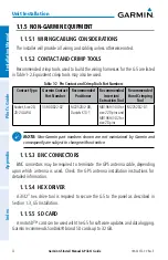
1.1.5 NON-GARMIN EQUIPMENT
1.1.5.1 WIRING/CABLING CONSIDERATIONS
The installer will provide all wiring and cabling unless otherwise noted.
1.1.5.2 CONTACT AND CRIMP TOOLS
Recommended crimp tools used to build the wiring harnesses for the G5 are listed
in Table 1-2. Equivalent crimp tools may also be used.
Table 1-2 Pin Contact and Crimp Tools Part Numbers
Contact Type
Garmin Contact
Part Number
Recommended
Positioner
Recommended
Insertion/
Extraction Tool
Recommended
Hand Crimping
Tool
Socket, Size 20,
20-24 AWG
336-00022-02
M22520/2-08,
Daniels K13-1
M81969/1-04 for
size 22D pins and
M81969/1-02 for
size 20 pins
M22520/2-01
NOTE:
Non-Garmin part numbers shown are not maintained by Garmin and
consequently are subject to change without notice.
1.1.5.3 BNC CONNECTORS
BNC connectors may be required to terminate the GPS antenna cable, depending
upon which antenna is used. Check the GPS antenna installation instructions for
detailed information.
1.1.5.4 HEX DRIVER
A 3/32” hex drive tool is required to secure the G5 to the panel as described in
Section 1.3, G5 Installation.
1.1.5.5 SD CARD
A microSD™ card can be used with the G5 for software updates and data logging.
Garmin recommends SanDisk® brand SD cards up to 32 GB.
Summary of Contents for Approach G5 - GPS-Enabled Golf Handheld
Page 1: ...G5 Install Manual Pilot s Guide ...
Page 2: ...Blank Page ...
Page 3: ...INSTALLATION MANUAL PILOT S GUIDE APPENDIX INDEX ...
Page 4: ...Blank Page ...
Page 16: ...Garmin G5 Install Manual Pilot s Guide 190 02072 00 Rev E iv Table of Contents Blank Page ...
Page 237: ...Garmin G5 Install Manual Pilot s Guide 190 02072 00 Rev E Blank Page ...

