Garmin G5 Install Manual & Pilot's Guide
190-02072-00 Rev. E
16
Unit Installation
Installation Manual
Pilot's Guide
Appendix
Index
6)
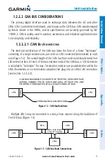
Verify that the CAN-H and CAN-L signals are not shorted to ground (this
can happen when shielded wire is installed incorrectly).
7)
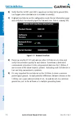
Highlight each device on the configuration mode Device Information page
and verify that the value displayed for Network Error Rate is a steady 0%.
Figure 1-11 Network Error Rate
8)
Power up only the #1 G5 unit and one other CAN device at a time, and
verify the connection quality for each device. Sometimes a device will
communicate only when it is the only powered device on the CAN bus, if
one or more of the above issues is present. Evaluating each CAN device in
turn can help narrow down a problem.
9)
It is very important for each device on the CAN bus to share a common
power/signal ground. Ground potential differences between devices on the
CAN bus can cause communication errors. Ground devices to a common
ground bus, not to the airframe or to multiple grounding buses.
Summary of Contents for Approach G5 - GPS-Enabled Golf Handheld
Page 1: ...G5 Install Manual Pilot s Guide ...
Page 2: ...Blank Page ...
Page 3: ...INSTALLATION MANUAL PILOT S GUIDE APPENDIX INDEX ...
Page 4: ...Blank Page ...
Page 16: ...Garmin G5 Install Manual Pilot s Guide 190 02072 00 Rev E iv Table of Contents Blank Page ...
Page 237: ...Garmin G5 Install Manual Pilot s Guide 190 02072 00 Rev E Blank Page ...

