
Garmin G5 Install Manual & Pilot's Guide
190-02072-00 Rev. E
36
Unit Installation
Installation Manual
Pilot's Guide
Appendix
Index
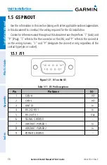
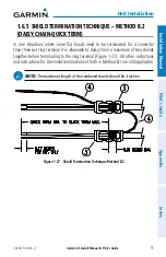
1.5 G5 PINOUT
Use the information in this section (along with other applicable sections/appendices
in this document) to construct the wiring required for the G5 installation.
Connector references used throughout this document use the prefixes "J" (Jack) and
"P" (Plug). "J" refers to the the connector on the LRU, and "P" refers to the connector
on the wiring harness. "J" and "P" designate the connector only, regardless of the
contact type (pin or socket).
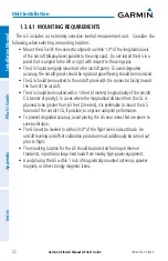
1.5.1 J51
5
1
9
6
Figure 1-21 J51 on the G5
Table 1-11 J51 Pin Descriptions
Pin
Pin Name
I/O
1
CAN-H
I/O
2
CAN-L
I/O
3
UNIT ID
In
4
RS-232 RX 1
In
5
RS-232 TX 1
Out
6
SIGNAL GROUND
--
7
AIRCRAFT POWER 1
In
8
AIRCRAFT POWER 2
In
9
POWER GROUND
--
Summary of Contents for Approach G5 - GPS-Enabled Golf Handheld
Page 1: ...G5 Install Manual Pilot s Guide ...
Page 2: ...Blank Page ...
Page 3: ...INSTALLATION MANUAL PILOT S GUIDE APPENDIX INDEX ...
Page 4: ...Blank Page ...
Page 16: ...Garmin G5 Install Manual Pilot s Guide 190 02072 00 Rev E iv Table of Contents Blank Page ...
Page 237: ...Garmin G5 Install Manual Pilot s Guide 190 02072 00 Rev E Blank Page ...