


Reviews:
No comments
Related manuals for GSU 75 Series
VX2409
Brand: ViewSonic Pages: 25
VG2433Smh
Brand: ViewSonic Pages: 25
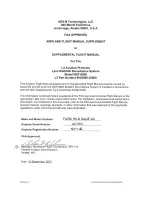
L3 9029000-20000
Brand: L3 Aviation Products Pages: 27

COLUMBUS
Brand: VALERA Pages: 2

GPSMAP 800 Series
Brand: Garmin Pages: 22

Dreamoc Diamond
Brand: Realfiction Pages: 8

X325BV-FMQC
Brand: Sceptre Pages: 56

REYHAN CL
Brand: GGMgastro Pages: 18

6040 Series
Brand: CIAM Pages: 19


