Garmin G5 Install Manual & Pilot's Guide
190-02072-00 Rev. E
14
Unit Installation
Installation Manual
Pilot's Guide
Appendix
Index
1.2.2.2.5 Can B
uS
i
nStaLLation
G
uideLineS
For maximum reliability of the CAN bus, the following guidelines should be followed:
• The CAN bus backbone must be a single linear path with exactly two distinct
ends. CAN bus connections should be daisy-chained from device to device.
Avoid “T”, “Y”, and "star" topologies, and do not use a hub device (Figure
1-5).
• The overall length of the bus should not exceed 66 feet (20 meters).
• Keep all stub node connections as short as practical. The maximum length of
any stub node connection is 1 foot (0.3 meter).
• Avoid connecting more than one device to the CAN bus backbone at the
same point. Instead, daisy chain the CAN bus backbone from one device to
the next.
• Observe proper wiring, shielding, and grounding requirements described in
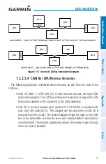
• Terminate the CAN bus at the two extreme ends of the bus, as described in
• When adding a new device to the CAN bus, evaluate proposed modifications
to the CAN bus wiring connections to ensure compliance with all of the
preceding requirements.
Summary of Contents for Approach G5 - GPS-Enabled Golf Handheld
Page 1: ...G5 Install Manual Pilot s Guide ...
Page 2: ...Blank Page ...
Page 3: ...INSTALLATION MANUAL PILOT S GUIDE APPENDIX INDEX ...
Page 4: ...Blank Page ...
Page 16: ...Garmin G5 Install Manual Pilot s Guide 190 02072 00 Rev E iv Table of Contents Blank Page ...
Page 237: ...Garmin G5 Install Manual Pilot s Guide 190 02072 00 Rev E Blank Page ...


