Garmin G5 Install Manual & Pilot's Guide
190-02072-00 Rev. E
47
Unit Installation
Installation Manual
Pilot's Guide
Appendix
Index
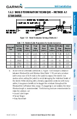
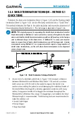
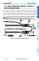
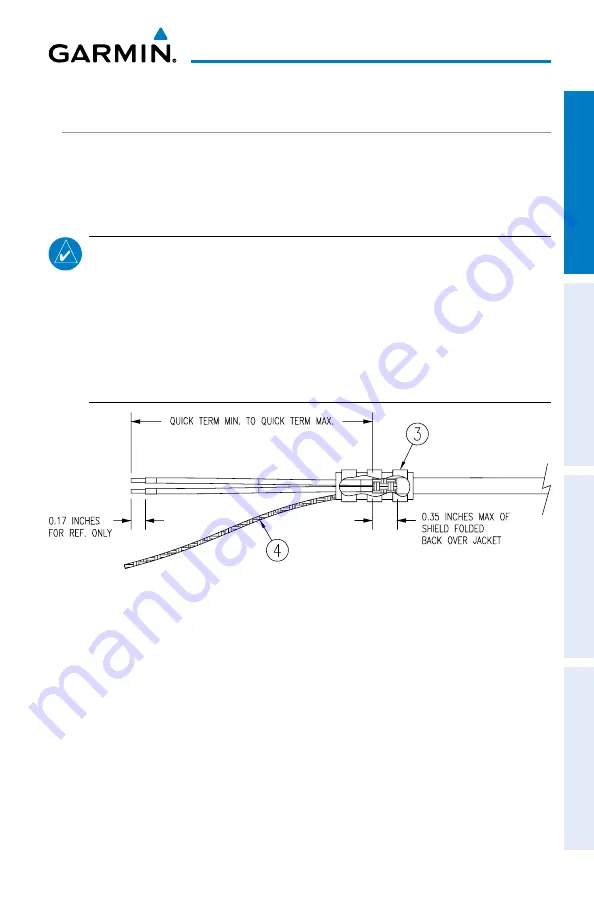
1.6.4 SHIELD TERMINATION TECHNIQUE – METHOD B.1
(QUICK TERM)
If desired, the drain wire termination (item 3, Figure 1-22) and the floating shield
termination (item 5, Figure 1-22) can be effectively combined into a “Quick Term”.
This method eliminates the float in the cable insulation and moves the placement of
the window described in Method A.1. This technique is depicted in Figure 1-26.
NOTE:
T
he
original purpose for separating the shield drain termination from the
float termination in Method A.1 was to allow for a variety of lengths for the drain
wires such that the shield drain terminations would not all bunch up in the harness
and to eliminate loops in the drain wires. If Method B.1 is used, care must be
taken to ensure that all drain shield terminations can still be inspected. Garmin
recommends using Method A.1 on connectors which require a large number of
shield drain terminations, as this will allow these terminations to be dispersed
across a larger area.
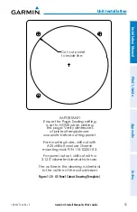
Figure 1-26 Shield Termination Technique Method B.1
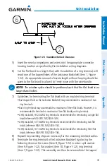
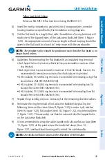
1) At one end of a shielded cable (item 2, Figure 1-22) measure a distance
between Window Min and Window Max (Table 1-16) and cut a window
(with a max size of 0.35 inch) in the jacket to expose the shield. Use
caution when cutting the jacket to avoid damaging the individual braids of
the shield. When dealing with a densely populated connector with many
cables, it may prove beneficial to stagger the windows throughout the
Window Min to Window Max range. If staggering is not needed, the Ideal
Window length is recommended. The following tools are recommended to
make the window cut:
• Coaxial Cable Stripper
• Thermal Stripper
• Sharp Razor Blade
Summary of Contents for Approach G5 - GPS-Enabled Golf Handheld
Page 1: ...G5 Install Manual Pilot s Guide ...
Page 2: ...Blank Page ...
Page 3: ...INSTALLATION MANUAL PILOT S GUIDE APPENDIX INDEX ...
Page 4: ...Blank Page ...
Page 16: ...Garmin G5 Install Manual Pilot s Guide 190 02072 00 Rev E iv Table of Contents Blank Page ...
Page 237: ...Garmin G5 Install Manual Pilot s Guide 190 02072 00 Rev E Blank Page ...


